

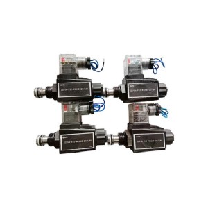
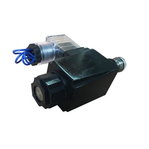
The 22FDA-K2T-W110R-20/LBO is a test solenoid valve used in the governing and emergency trip system of steam turbines. Its specific job is to simulate trip conditions while the turbine is under load — not to shut the unit down, but to confirm that the critical valves protecting it are free to move and will respond correctly if a real trip is ever demanded.
Where This Solenoid Valve Sits in the ETS Architecture
Steam turbine emergency trip systems typically use high-pressure EH oil — or in some designs, low-pressure turbine oil — to hold protective valves open during normal operation. When a trip occurs, the oil pressure is vented and the valve springs force closure. The trip solenoid valve is the electrical actuator that initiates that venting.
The 22FDA-K2T-W110R-20/LBO solenoid valve is energised-to-trip in its configuration — meaning it closes the EH oil supply path when its coil is energised. This is the opposite of most conventional hydraulic control solenoid valves in a DEH system, which are energised to open. That inversion of logic is central to understanding how the test function works without causing an actual turbine trip.
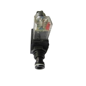
In ETS architecture, multiple trip solenoid valves are typically arranged in a voting matrix — two-out-of-three, or similar — so that a single solenoid valve actuation during a test can be isolated from the full trip chain. The 22FDA-K2T-W110R-20/LBO operates within that structure, allowing one leg of the protection system to be functionally tested while the remaining legs continue to hold the turbine in normal protective status.
What “Online Testing” Actually Means for a Trip Solenoid Valve
An online test of a trip solenoid valve is not the same as tripping the turbine. The distinction is mechanical as well as logical. When the test solenoid valve is energised during an online partial stroke test, it interrupts the EH oil supply to a specific section of the hydraulic circuit serving a main stop valve or control valve. That valve begins to close — but only partway.
The test logic includes a position-based cutoff. Once the valve under test has moved a defined partial stroke — typically 10–20% of full travel, depending on system design — the test sequence stops. The solenoid valve de-energises, EH oil pressure is restored, and the tested valve returns to its fully open position. The entire sequence takes seconds.
What the test confirms is that the valve is not seized. A main stop valve that has been stationary at full open under high steam pressure and temperature for months or years can develop oxide-based friction at the seat or guide surfaces. If it seizes, it will not close during an actual trip — the most critical failure mode in turbine protection. The online partial stroke test is the only way to detect that condition without shutting the unit down.
The Solenoid Valve’s Role in the Test Sequence
The 22FDA-K2T-W110R-20/LBO initiates the test by switching the hydraulic state of the circuit on command from the ETS logic controller. When energised, it blocks the EH oil supply path to the actuator of the valve being tested. The actuator spring load then begins to move that valve toward closed.
Throughout the test, the position transmitter on the valve under test feeds real-time position data back to the controller. The controller is watching for two things: that the valve has moved (confirming it is not seized), and that the movement rate matches the expected closure speed profile. Closure time is one of the key parameters — a valve that moves but takes twice as long as its specification to reach the partial stroke position has increased friction somewhere that needs investigation.
When the position threshold is reached, the ETS logic commands the test solenoid valve to de-energise. EH oil is restored to the actuator, and the tested valve reopens. The controller logs the result — stroke completed, closure time within limits, reopening confirmed — and the test is recorded as passed or flagged for review.
If the tested valve does not move within a defined timeout period, the ETS logic generates an alarm. At that point, the system does not automatically proceed to a full trip, but it does flag the valve as potentially seized and requires operator decision on next steps.
The Bypass Interlock Requirement: What Makes Turbine Testing Different
This is where the test logic for a steam turbine trip solenoid valve diverges significantly from testing a conventional hydraulic control valve in a standard industrial process system.
In a conventional hydraulic circuit, testing a solenoid valve that controls a flow or pressure regulation function might mean briefly switching the solenoid while the process runs on a parallel path or a controller holds the output stable through other means. The consequence of a brief interruption in one control path is a small perturbation that the system absorbs.
A steam turbine main stop valve is not a flow regulation device. It is a full-authority shut-off valve. If it closes fully during an online test — even unintentionally — it removes steam from the turbine cylinders, load drops immediately, and depending on the speed of closure and the load level, it can trigger a full unit trip through the speed and load protection systems.
How the Bypass Interlock Prevents a Test-Induced Trip
Before the test solenoid valve is energised during an online partial stroke test, the ETS logic must confirm that the bypass interlock condition is satisfied. This typically involves two elements working together:
- Partial stroke limit, not full stroke: The test sequence is programmed to restore oil pressure before the valve reaches a closure position that would cause a load disturbance. The interlock monitors valve position in real time and will abort the test — restoring EH oil immediately — if the valve travel exceeds the test limit. This is a hard interlock, not a soft alarm.
- Remaining trip legs in service: In a two-out-of-three or similar voting architecture, the test solenoid valve for one leg of the protection system can be exercised because the other two legs remain in their protective state. If one of those remaining legs is also in a test or maintenance bypass condition, the test on the 22FDA-K2T-W110R-20/LBO must be deferred. Testing two legs simultaneously removes the logical redundancy that keeps the unit protected during the test.
The key difference from a standard hydraulic solenoid valve test is that the turbine system does not rely on a parallel process path or a controller adjustment to absorb the test. It relies on a combination of position-limited stroke control and protection system redundancy — both managed through the ETS logic, with the test solenoid valve as the physical actuator of the test.
Load Level Considerations
Most turbine ETS programmes specify a minimum load level below which online partial stroke testing is permitted. At very high load, a main stop valve moving even 10% toward closed produces a more significant and faster steam flow reduction than the same movement at partial load. The test window is typically set between 20% and 80% of rated load, with the exact limits determined by the OEM’s governing system analysis for that specific unit.
Some systems also require a hold on automatic load control during the test sequence — switching the DEH controller to a fixed reference for the duration — to prevent the speed governor from opening other steam admission valves to compensate for the test-induced flow reduction, which could mask the test result or produce an uneven response.
Test Frequency and What the Records Show
Online partial stroke tests using the 22FDA-K2T-W110R-20/LBO are typically scheduled at intervals of one to three months, depending on the plant’s maintenance programme and any regulatory or insurance requirements for turbine protection system testing. The frequency is driven by the need to detect slow-developing valve seizure before it progresses to the point where the valve would fail to respond in a real trip.
The test records carry more information than a pass/fail flag. Trending closure time across multiple test cycles on the same valve is one of the most useful diagnostic tools available without opening the valve for inspection. A valve whose closure time is increasing cycle over cycle is developing friction at a measurable rate — that trend, if continued, will eventually fail the time criterion and flag a maintenance need before the valve actually seizes.
| Test Parameter | What It Confirms | Action if Outside Limit |
|---|---|---|
| Valve movement detected within timeout | Valve is not seized at rest position; free to move from full open | Alarm generated; valve flagged for immediate inspection; test not repeated until investigated |
| Closure time to partial stroke position | Friction and hydraulic actuator response are within acceptable limits | Trending increase warrants lubrication or inspection at next outage; hard limit breach flags valve for removal |
| Valve reopening confirmed | Actuator is restoring correctly after test; EH oil circuit to actuator is functional | Failure to reopen fully triggers alarm; solenoid valve and actuator circuit checked before next test |
| Test solenoid valve response time | The 22FDA-K2T-W110R-20/LBO itself responded within specification on energisation | Slow solenoid response may indicate coil degradation or hydraulic restriction; solenoid valve inspected |
| ETS leg status during test | Remaining protection legs were in normal state throughout the test | If a second leg was in bypass during test, record flagged and test validity reviewed |
Electrical Specification and Coil Reliability
The designation “W110R” in the part number indicates a 110V AC coil — important to verify against the site’s ETS panel supply voltage before installation. The “20″ suffix typically refers to the port size or flow coefficient, and “LBO” indicates a specific body and porting configuration. These suffix details are not interchangeable between variants, and fitting a coil-voltage mismatch can cause the solenoid valve to operate outside its designed switching speed or fail to hold its energised state reliably.
Coil reliability on a test solenoid valve matters differently than on a continuously operating control valve. The 22FDA-K2T-W110R-20/LBO is energised briefly during each test cycle — seconds, not hours. But it must respond within milliseconds when commanded, every time, including after months of sitting in the de-energised state between tests. Coil insulation resistance checks at each scheduled test interval, and replacement on a defined life cycle rather than waiting for failure, are consistent with how most ETS programmes manage these components.
Distinguishing the Test Solenoid from the Trip Solenoid in the Same Circuit
Some ETS designs use separate solenoid valves for the test function and the actual trip function. In that arrangement, the test solenoid valve — the 22FDA-K2T-W110R-20/LBO in this application — controls a branch circuit that allows partial stroke testing of the protected valve without touching the main trip solenoid valve. The main trip solenoid remains in its fully armed state throughout the test.
In other designs, the trip solenoid valve itself is the one being tested via the partial stroke logic — it is energised briefly and the downstream actuator is monitored. The distinction between these two architectures matters for how the test results are interpreted and which component’s response time is being measured by the test sequence.
Knowing which architecture your unit uses is necessary for correctly diagnosing a test anomaly. A slow response time flagged during a test could indicate slow coil response in the test solenoid valve, a restriction in the hydraulic branch circuit, friction in the protected valve, or a combination. The test record alone doesn’t always identify the source — but it does identify that something in the chain needs closer attention.
Post time: May-28-2026
-

Steam Turbine Shutoff valve F3RG03D330
-

EH oil online filter machine fine filter JLX-30...
-

Epoxy-ester air-drying red insulating varnish 9130
-

Vacuum pump rocker seal P-1764-1
-

23D-63B steam turbine turning solenoid valve
-

Hydraulic oil filter element LX-HXR25X20
-

Insulation Alkali-Free Fiberglass tape ET60
-
RTV Silicon steel sheets adhesive J0705
-

SM4-20(15)57-80/40-10-S182 actuator electro-hyd...
-

Steam Turbine Rotation Speed Monitor HZQS-02H
-

WJ series hydrogen system bellows globe valve
-

Platinum Resistor Temperature Sensor WZPM-201