

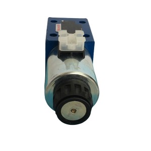
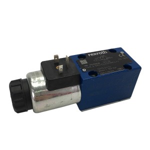
The MFB-2.5YC is an AC 220V wet-type solenoid valve coil designed to drive hydraulic directional solenoid valves in demanding continuous-duty environments. It sees service in steam turbine EH oil control systems, jacking oil circuits, and various hydraulic actuator control branches — applications where coil reliability directly affects whether a valve responds when commanded.
Design and Application Context
The “wet-type” designation in MFB series coils means the coil assembly is in direct contact with the hydraulic fluid in the valve body — the coil and solenoid plunger sit inside the oil-filled cavity rather than being isolated from it by an external tube. This construction removes the need for a separate sealed tube between the magnetic circuit and the fluid, which simplifies the assembly and improves heat transfer from the coil to the surrounding oil.
That heat transfer to oil is one of the design’s thermal management advantages. In a properly functioning system where the directional solenoid valve cycles normally or holds a stable position with a clean spool, the surrounding hydraulic oil absorbs and dissipates heat from the coil continuously. The coil body temperature stays within the rated insulation class limits.
In turbine EH oil and jacking oil systems, the MFB-2.5YC coil drives directional valves that control oil routing to actuators, selector circuits, or isolation functions. These are not high-cycle applications — many of these solenoid valve coils sit energised in a fixed state for long periods, with only occasional switching. That characteristic has implications for how coil thermal conditions develop and how early signs of trouble appear.
What Happens When the Valve Spool Sticks
Hydraulic directional solenoid valves depend on the spool moving freely through its full stroke when the coil energises. In EH oil systems using phosphate ester fluid, oil degradation over time produces varnish and sludge deposits that accumulate on valve spool lands and in the bore. Mechanical wear between the spool and bore can also create debris that packs into clearance gaps. Either condition can leave the spool stuck partway through its stroke rather than completing full travel.
A spool stopped at an intermediate position is a problem in two directions. Hydraulically, the port geometry is misaligned — some paths are partially open when they should be closed, or partially blocked when they should be open. The result is internal leakage and slow, inconsistent valve response. From the coil’s perspective, the situation is more serious.
In a wet-type AC solenoid coil, the electromagnetic force required to hold the plunger at the fully energised position is substantially lower than the force required to pull it in from the de-energised position. When the spool sticks mid-stroke, the plunger is held at a position where the magnetic air gap is larger than its full-stroke value. The coil draws significantly higher current trying to maintain that position against the gap. More current means more heat — and in a stalled or stuck condition, that heat is generated continuously.
The oil’s ability to carry that heat away may not keep pace with the generation rate. Coil body temperature climbs. Over time — not hours, but days or weeks of a stuck spool going unnoticed — the enamel insulation on the magnet wire inside the coil undergoes accelerated thermal degradation. The insulation softens and breaks down at a molecular level. Once the insulation between adjacent winding turns is thin enough, a turn-to-turn short develops. Current flows through the short path, resistance drops, current increases, heat increases, and the failure mode accelerates to coil burnout.
Undervoltage: The Hidden Thermal Risk
The MFB-2.5YC is rated for AC 220V supply. The lower operating limit is generally taken as 85% of rated voltage — 187V in this case. Below that threshold, the coil’s pulling force drops to the point where the solenoid plunger may not complete its full stroke, or may complete it slowly enough that valve response time falls outside acceptable limits.
Undervoltage in field installations is more common than it appears on paper. Long cable runs from the distribution panel to junction boxes at the valve manifold introduce resistive voltage drop. Where multiple solenoid valve coils share a common supply circuit, simultaneous energisation can pull the local voltage below the nominal value. Poor terminal connections — oxidised crimps, loose screw terminals — add further drop at the point of connection.
The thermal consequence of sustained undervoltage is less obvious than the response-time consequence, but it runs in parallel. An AC solenoid coil operating below its designed voltage draws higher current than nominal to develop the required magnetic force — the relationship between voltage and current in an inductive coil means lower voltage produces higher current for the same force output. That elevated current produces more heat in the winding. If the voltage shortfall is chronic and undetected, the coil runs warm permanently. Insulation life is reduced, quietly and continuously, until an early failure ends the coil’s service life.
Detecting Coil Stress Without Instruments: Temperature and Sound
Not every plant has continuous coil temperature monitoring or current logging on every solenoid valve circuit. In practice, the first indication of a thermal or electrical problem often comes from a technician’s direct observation during a routine walk-down. Two indicators are accessible without any measurement equipment.
Surface Temperature as a Diagnostic Signal
An MFB-2.5YC coil in normal operation running at rated voltage with a freely moving spool will be warm to the touch — this is expected for a continuously energised AC coil. The temperature is typically in the 40–60°C range above ambient for a healthy coil, depending on ambient conditions and duty cycle.
A coil that is noticeably hotter than others in the same cabinet or on the same manifold — or one that is too hot to hold a hand against for more than a second or two — is generating heat beyond its normal operating level. That excess heat is coming from somewhere: elevated current draw from undervoltage, higher winding resistance from partial insulation breakdown, or increased magnetic losses from a stuck plunger in a high-gap position.
A contact thermometer or infrared thermometer gives a number. Without instruments, the comparison between coils on the same manifold — where ambient conditions and energisation state are similar — is a useful first screening. A coil running significantly hotter than its neighbours warrants a follow-up measurement and a check of the valve spool condition.
Actuation Sound as a Voltage Indicator
When a directional solenoid valve coil energises and the plunger moves to its full-stroke position, there is a characteristic mechanical click or thud as the plunger seats in the energised position. The quality and timing of that sound changes under undervoltage conditions.
At rated voltage, the actuation is prompt — the click is sharp and occurs within a short time of energisation. As supply voltage drops, the plunger’s acceleration decreases. The closing sound becomes softer, slower, or in some cases splits into a drawn-out movement sound followed by a delayed seating sound rather than a single crisp closure. At voltages close to the lower operating limit, the plunger may audibly struggle to complete its stroke.
An experienced technician walking through a valve gallery during normal switching operations can identify these sound changes without instruments. The comparison between solenoid valve coils on the same circuit during simultaneous or sequential energisation is particularly telling — if one coil sounds different from the others under the same supply conditions, it warrants voltage measurement at the terminal block.
Diagnosing the Failure Mode: A Practical Reference
| Observed Condition | Likely Cause | Recommended Action |
|---|---|---|
| Coil surface very hot; slow or no valve response | Valve spool stuck mid-stroke; coil drawing excess current against large air gap | De-energise immediately. Isolate the valve circuit. Inspect spool for varnish or debris. Check oil cleanliness in the EH system. Do not re-energise until spool moves freely. |
| Coil surface warm but hotter than adjacent coils; valve response within limits | Supply voltage below nominal; coil running at elevated current; early thermal stress | Measure terminal voltage during energisation. Check cable and terminal condition. If voltage is below 187V, investigate drop source before next scheduled maintenance. |
| Actuation sound soft or delayed; response time increasing | Undervoltage at coil terminals; plunger pulling force insufficient for clean stroke | Measure supply voltage at coil terminals under load. Check terminal connections. Isolate cause of voltage drop — cable resistance, shared circuit loading, or connection resistance. |
| Coil draws high current but valve does not respond | Spool fully seized; coil plunger cannot move regardless of electromagnetic force | Remove and inspect valve. Replace coil if winding temperature has been elevated — insulation may already be compromised even if coil still passes continuity test. |
| Coil fails continuity test; resistance very low or open circuit | Turn-to-turn short circuit (low resistance) or broken winding (open circuit) — both result from insulation failure | Replace coil. Investigate root cause before installing replacement — a new coil in the same fault condition will fail again. Check spool, voltage, and oil condition. |
| Intermittent valve response with no clear pattern | Marginal voltage with variable load on shared supply; partial spool stiction that clears intermittently | Log voltage and current over several operating cycles. Pull oil sample from the hydraulic circuit for cleanliness check. Intermittent faults are harder to diagnose but the same root causes apply. |
Coil Replacement Interval and Condition-Based Maintenance
The MFB-2.5YC coil does not have a fixed replacement interval in the way that a filter element or a seal kit does. Its service life depends on the actual operating conditions — ambient temperature, supply voltage quality, switching frequency, and the mechanical condition of the valve spool it drives. A coil in a clean, correctly supplied circuit with a well-maintained valve can last many years. One operating in the adverse conditions described above may fail within a fraction of that time.
Condition-based maintenance is the more appropriate framework for these components. The key checkpoints at each planned maintenance interval are:
- Measure insulation resistance of the coil winding to ground (megohmmeter test). A healthy coil shows resistance well above 1 MΩ. A degraded winding shows markedly lower values, often without any obvious external sign of failure.
- Measure winding resistance and compare against the coil’s rated DC resistance specification. An increase in resistance indicates partial open-circuit conditions in the winding; a decrease suggests turn-to-turn shorting.
- Verify terminal voltage at the coil terminals — not at the panel — during normal energisation. Record and trend these values across maintenance intervals.
- Check the spool for freedom of movement when the valve is de-energised and isolated. Manual push-rod testing, where the valve design permits, gives a direct indication of spool drag.
Keeping records of coil resistance and insulation readings across multiple maintenance visits provides the trend data needed to make a replacement decision before failure, rather than in response to one.
E-mail: sales@yoyik.com
Tel: +86-838-2226655
Whatsapp: +86-13618105229
Yoyik offers various types of power plants spare parts for steam turbines, generators, boilers as below:stainless steel solenoid valve SV13-12V-O-0-00
Solenoid valve M-3SEW6U36/420MG26N9K4QMAG24/V
cover plate HGPCV-02-B10
solenoid coil 230vac price 3D01A009
Pump P.SL63/45B
accumulator bladder NXQ-A-32/31.5-LY-3
pump HSNSQ3440-46
PUMP MAIN PVH098R01AJ03A250000002001AB010A
Pump P.SL63/45A
Servo G772K240A
24v solenoid valve GS060600V
Pressure Relief Valve YSF9-70/130KKJ
pump CBT-F416-AF*9
solenoid 220v VFS5210-4DB
screw pump case HSNH660-40NZ
Oil pump GPA2-16-E-30-R
sealing oil re-circulating pump repair kit HSNH280-43NZ
Mecanical seal DFB80-80-240H
blader DS40P150.055
small gear pump CB-B200
Post time: May-28-2026
-

Fire-resistant oil filter DP401EA01V/-F
-

TDZ-1E series linear displacement transducer LV...
-

Gas turbine actuator oil filter CB13299-001V
-

25CCY14-190B Jacking oil axial piston pump
-

CS-1 Series Rotational Speed Sensor
-

Recycle pump working filter DP1A401EA03V/-W
-

Cellulose filter element LX-DEA16XR-JL
-

Intelligent Reversal Speed Monitor JM-D-5KF
-

Steam turbine precision filter MSF-04S-03
-

RTD thermocouple temperature sensor probe WZP2-231
-

Boiler Water level indicator electrode DJY2212-115
-

EH oil actuator filter DP6SH201EA03V/-W for Ste...