

Steam turbines expand when they heat up — everyone working in a power plant knows that. The real question isn’t whether the casing moves, it’s whether it’s moving the way it should. Is the expansion happening evenly on both sides? Is the casing sliding freely along its key system, or is something holding it back? The BT-50 absolute expansion sensor exists to answer those questions, constantly, while the unit is running.
This article gets into how the BT-50 works, why sensor placement around the turbine’s dead point matters more than most people realize, and — probably the most practically useful part — how to figure out whether an abnormal differential reading on your DCS is a real mechanical problem or just a sensor acting up.
How the BT-50 Expansion Sensor Works
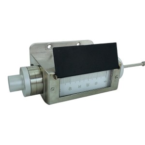
The BT-50 uses an LVDT — a linear variable differential transformer — as its measuring element. LVDTs have been used in precision displacement measurement for decades, and for good reason. They produce a clean analog output that tracks displacement linearly, they don’t wear out from mechanical contact the way some other sensor types do, and they tend to hold their calibration well over long service periods.
The way the BT-50 is set up is fairly straightforward. A probe rod connects the sensor body to the turbine casing. When the casing expands — during startup, load changes, or temperature shifts — the rod moves inside the LVDT, and the sensor converts that movement into a signal. That signal goes to a monitoring instrument, which turns it into a displacement reading in millimeters.
Two sensors are used, one on each side of the turbine’s dead point. The monitoring system looks at both readings and calculates the difference. That differential value is what tells you about casing deformation — specifically, how evenly the casing is expanding relative to its fixed reference.
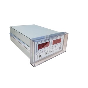
When the differential climbs past the alarm setpoint, the monitoring instrument sends a switch signal to the protection system. Depending on the configuration, that can mean an alert, a load reduction, or a trip. The setpoint itself is usually set during commissioning based on the turbine manufacturer’s allowable deformation limits.
The Dead Point — and Why It’s the Reference Everything Else Is Built Around
The dead point is the location on the turbine casing that doesn’t move during thermal expansion. Every other part of the casing shifts as temperatures rise and fall — the dead point stays fixed relative to the foundation.
This happens because of the sliding key system (sometimes called slip keys or sliding pins, depending on who made the turbine). The sliding key system constrains how the casing is allowed to move. It lets the casing expand axially and laterally, but it anchors the casing at one specific location. That anchor location is the dead point.
On most steam turbines, the dead point sits at the bearing pedestal nearest the generator end, where the casing is rigidly connected to the foundation. The exact location, though, should always come from the manufacturer’s alignment drawings. It’s not something to estimate or assume in the field.
Where Exactly the BT-50 Sensors Should Be Mounted
The sensors go on either side of the dead point — that’s the whole point of using two of them. With one sensor on each side, the differential reading reflects how the casing is expanding around that fixed reference. If both sensors were on the same side, you’d just be comparing two nearby points on the same moving surface, which tells you very little about actual casing deformation.
Alignment matters too, and it’s easy to get wrong. The probe rod has to be oriented along the direction the casing actually moves. If the rod is angled even a few degrees off, you get a cosine error — the sensor only captures part of the true displacement, not all of it. That kind of error shows up as a consistent underreading, which can make the casing look like it’s expanding less than it really is.
Symmetric placement around the dead point is also important. If both sensors end up shifted toward the same end of the turbine — even slightly — the readings won’t cancel properly during normal expansion, and you’ll end up with a persistent offset that looks like a real alarm condition. It’s a subtle installation issue, but it causes real operational headaches.
Reading the Numbers — What Normal Looks Like and What Doesn’t
During a normal startup, the differential reading between the two BT-50 sensors will move around. The casing doesn’t heat up perfectly evenly, and some asymmetry during the warm-up phase is expected. What you’re looking for is that the value stabilizes once the unit reaches steady load and the casing temperature distribution settles out.
A differential that keeps climbing at steady load — or one that spikes suddenly without any corresponding change in operating conditions — is the kind of thing that needs attention. Same goes for a reading that doesn’t return to its baseline after a thermal cycle. These are the patterns that either point to a real mechanical issue or suggest something’s off with the sensor itself.
Sorting Out Whether It’s a Mechanical Problem or a Sensor Fault
This is the part that matters most to the people actually working with this equipment day to day. The DCS shows the differential between the two BT-50 sensors going up. Is the casing sliding key system seizing? Or is one of the sensors lying to you?
Getting this wrong in either direction is costly. Chase a sensor fault as a mechanical problem and you’re looking at unnecessary shutdowns and investigation work. Dismiss a real seizure as a sensor issue and you risk serious damage to the turbine internals — blade rubs, seal damage, clearance problems that don’t show up until the next outage.
There’s no single test that gives you the answer instantly, but working through the following checks in order gets you there without wasting time.
Look at the Individual Sensor Readings First
Don’t just look at the differential. Pull up the individual BT-50 readings on the DCS and watch them during a period of stable conditions. If one sensor is drifting while the other holds steady, that’s a sensor problem, not a casing problem. Zero drift in an LVDT-based expansion sensor usually comes from signal conditioning issues, temperature effects on the electronics, or a loose cable connection somewhere in the circuit.
If both sensors are moving together in a way that makes physical sense — one side expanding more than the other, consistently, with the differential growing gradually — that’s more consistent with a real mechanical constraint developing.
Check Whether the Probe Rod Is Moving Freely
The probe rod on the BT-50 has to move with the casing. If it’s seized — stuck from corrosion, contamination, or physical damage — it won’t track casing movement correctly. A seized probe rod tends to produce a reading that stays flat even when the casing is clearly moving, or it produces a sudden jump in the reading rather than a smooth change.
This is different from what you’d see with actual sliding key seizure. With casing seizure, one side of the casing is being held while the other continues to expand — so you’d expect one sensor to show increasing displacement while the other stays relatively flat. With a stuck probe rod, the affected sensor holds constant regardless of what the casing is actually doing.
Inspect the Cable Runs and Terminal Connections
Turbine halls are harsh environments — vibration, heat, moisture. All of those work on cable connections over time. Loose terminal screws or moisture ingress at junction boxes produce erratic, noisy readings rather than smooth trends. If the differential signal is jumping around without any pattern, or if it changes suddenly in a way that doesn’t correlate with anything else happening in the unit, the cable run is worth checking before anything else.
This is one of those checks that takes a short time but regularly turns up the actual cause of what looked like a complicated problem.
Cross-Check Against Other Instruments
A sliding key seizure doesn’t happen in a vacuum. It affects how the casing distributes heat, how the rotor and casing move relative to each other, and sometimes how bearing temperatures behave. If the BT-50 differential is climbing but differential expansion, bearing temperatures, and casing temperature distribution all look normal, the evidence strongly points to a sensor or signal fault rather than a real mechanical problem.
On the other hand, if bearing temperatures are trending up asymmetrically, differential expansion is heading toward its alarm limit, and the BT-50 readings are physically consistent with a constrained casing — that’s a different situation entirely.
Quick Reference: Fault Patterns and What They Point To
| What You’re Seeing | More Likely Cause | Where to Start |
|---|---|---|
| One sensor drifting, the other stable | Sensor zero drift or electronics fault | Signal conditioning circuit, cable connections |
| One sensor flat, one changing normally | Probe rod seized on the flat sensor | Mechanical freedom of probe rod |
| Both sensors jumping erratically | Cable or terminal contact fault | Junction boxes, terminal screws, cable continuity |
| Differential rising steadily, other data also abnormal | Sliding key system seizure | Bearing temps, differential expansion, casing temp distribution |
| Differential spikes, everything else looks normal | Sensor or signal path fault | Individual sensor readings, cable inspection |
Keeping the BT-50 Reliable Between Outages
The BT-50 expansion sensor doesn’t need a lot of routine attention, but a few things done consistently during planned outages make a real difference in avoiding unexpected faults.
One of the most useful habits is building a proper baseline during commissioning or right after a major overhaul. Record the individual sensor readings and the differential at cold, warm, and full-load conditions. When something looks off later, having that reference data makes it much easier to spot what’s actually changed — and where.
- Check probe rod condition and verify it moves freely through its full range during each outage
- Inspect cable terminal connections, especially in high-vibration areas of the turbine hall
- Confirm that sensor mounting brackets haven’t shifted relative to the dead point reference since the last inspection
- Compare cold zero readings against the commissioning baseline — drift here is an early warning sign
- Verify probe rod alignment hasn’t changed if any casing work was done during the outage
None of these checks take long. They’re the kind of things that get skipped when outage schedules are tight, and then come back as diagnostic headaches during the next operating period.
Selecting the BT-50 for a New or Replacement Installation
When you’re specifying the BT-50 for a new installation or replacing sensors on an existing unit, a few things need to be confirmed before ordering.
Measurement range first — the sensor’s travel has to cover the full expected casing expansion for your turbine, with some margin. Output signal type needs to match your monitoring instrument or DCS input card; typically 4–20 mA, but worth confirming. Environmental rating matters depending on where the sensor is physically located on the turbine.
For replacement installations, matching the output range of the original sensor avoids having to recalibrate the monitoring system and reconfigure alarm setpoints — which adds time and introduces opportunities for configuration errors.
If you’re working through a specification for a specific turbine and aren’t sure about compatibility, the supplier’s engineering team can usually sort that out quickly if you provide the turbine model and the monitoring instrument details. It’s a faster path than trying to reverse-engineer compatibility from data sheets alone.
Getting the BT-50 installed correctly and understanding what the readings actually mean are what make it a useful instrument rather than just another number on the DCS screen. The measurement itself is straightforward — the value is in knowing how to interpret it.
Post time: Jun-29-2026
-

Actuator inlet oil filter AP6E602-01D10V/-W
-

MFZ-4 steam turbine cylinder sealing grease
-

Regeneration device anion filter PA810-002D
-

Actuator Inlet Flushing Oil Filter DP301EA01V/-F
-

BFPM hydraulic coupling oil filter DU631.3080.2...
-

AST/OPC solenoid valve coil 300AA00086A
-

EH oil regeneration filter ZX-80
-

Generator RTV epoxy adhesive J0792
-

HDJ892 Generator hydrogen sealing slot sealant
-

Oil purifier filter element P2FX-BH-30X3
-

Hydraulic Accumulator NXQ-A-6.3/31.5-L-Y
-

Gas turbine actuator oil filter CB13299-001V