

When the speed display on a boiler feedwater pump or turbine tachometer goes blank, starts jumping around, or shows a speed that doesn’t match what the machine is doing, the question is always the same: is it the sensor, the cable, the power supply, or the monitor? Getting to the right answer quickly matters — a feedwater pump running without confirmed speed measurement is a situation nobody wants to leave unresolved.
The SMCB-01-10L60 is an active three-wire rotational speed sensor with built-in amplification and signal conditioning. It can measure from zero speed upward, handles frequency response up to 20 kHz or 30 kHz depending on the variant, and is built for the interference-heavy environments found in power plant rotating equipment installations. Because it’s an active sensor with its own internal electronics, the diagnostic approach is different from a passive reluctance probe — and that’s worth understanding before you start swapping parts.
What “Active” Means for Fault Diagnosis
A passive reluctance speed sensor generates its own signal from shaft movement and needs no external power. An active sensor like the SMCB-01-10L60 requires a DC supply — typically 12V or 24V depending on the application — to power its internal amplifier and signal shaping circuit. This means there are more things that can go wrong, but also more things you can actually measure in the field to figure out where the problem is.
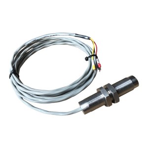
The three wires on this sensor are: power supply positive, common (negative/ground), and signal output. The signal output is a clean square wave or pulse train at a frequency proportional to shaft speed — not a raw sinusoidal voltage like a reluctance probe outputs. That shaped output is what makes the SMCB-01-10L60 suitable for long cable runs and noisy electrical environments, because the signal doesn’t degrade the way an analog voltage does over distance.
Knowing this wiring arrangement is the starting point for any field check.
The Four Things That Can Cause a Bad Reading
When a tachometer channel shows abnormal speed data, the fault is in one of four places. Working through them in order — from easiest to check to most involved — is the fastest route to the answer.
1. Power Supply Problem
This is the first thing to check because it’s the quickest and it eliminates the largest single failure category in one measurement. With a multimeter set to DC voltage, measure between the sensor’s positive supply wire and the common wire at the sensor connector or at the nearest accessible junction point.
The reading should be within the sensor’s specified supply voltage range — typically 12V ±10% or 24V ±10%. If the voltage is low, absent, or fluctuating, the sensor’s internal electronics aren’t getting what they need to work correctly. The sensor may not be faulty at all. Check the supply fuse, the power supply unit output, and any intermediate terminal connections in the cable run before going further.
A supply voltage that looks correct at the panel but is significantly lower at the sensor end points toward cable resistance or a poor connection somewhere in the run — particularly relevant on longer cable installations where voltage drop becomes a real factor.
2. Cable Damage or Connection Fault
Cable problems are common in power plant environments where cables route through areas with heat, vibration, and mechanical exposure. The failure modes vary — a complete break in one conductor, intermittent contact at a terminal, moisture ingress into a junction box causing leakage between conductors, or shield continuity loss that lets interference onto the signal wire.
With the sensor disconnected at both ends, a simple continuity check on each conductor with a multimeter identifies any open circuits. Check conductor-to-conductor and conductor-to-shield resistance as well — a low resistance between signal and supply wires, for example, points toward insulation damage from heat or mechanical abrasion.
Intermittent faults are harder to catch with a static continuity test. If the tachometer reading jumps around but occasionally looks correct, wiggling the cable along its length while watching the reading can reveal the fault location. A reading that changes when a specific cable section is disturbed tells you where to look more carefully.
3. Sensor Fault
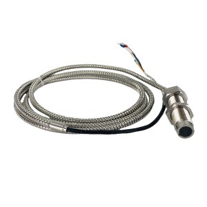
If the supply voltage at the sensor is correct and the cable checks out, the sensor itself is the next suspect. For an active speed sensor, the field test is straightforward: with the sensor powered up and the target wheel rotating at a known speed, measure the output signal on the signal wire.
Use a multimeter set to AC voltage or frequency measurement, or better yet a portable oscilloscope if one is available. With the shaft rotating, the signal wire should show a pulsing voltage alternating between near-zero and near-supply-voltage at the rotation frequency. No signal at all — just a constant voltage or zero voltage on the output wire — means the sensor’s internal circuit isn’t generating output. A signal that’s present but at the wrong frequency or with irregular pulse widths points toward a sensor with degraded internal electronics.
At zero speed or with the shaft stationary, the output should hold at a defined state — either high or low depending on whether a gear tooth or a gap is at the sensor face. If the output floats or oscillates with the shaft stationary, the sensor’s internal comparator circuit is likely faulty.
One practical check that doesn’t require the shaft to be rotating: pass a piece of ferrous steel slowly past the sensor face and watch the output. The output should switch cleanly each time the steel enters and exits the detection zone. If it doesn’t switch, or switches erratically, the sensor is not functioning correctly regardless of what the shaft speed readings look like.
4. Tachometer Channel Fault
If the sensor output signal measures correctly at the sensor end but the tachometer display is still showing wrong data, the fault is in the monitor channel — the input circuit, the internal processing, or the display. The way to confirm this is to compare what the sensor is actually outputting against what the tachometer is reporting.
If another channel on the same tachometer is available, temporarily connecting the sensor to that channel and checking whether the reading changes is a fast test. A correct reading on the alternate channel with the same sensor and cable confirms the original channel has a problem. If the alternate channel shows the same wrong data, the sensor or cable is still the more likely fault despite the earlier checks.
Field Testing Summary
| Symptom | First Check | Likely Cause |
|---|---|---|
| No signal at all, display blank | Supply voltage at sensor connector | Power supply failure, blown fuse, open cable conductor |
| Signal jumping / erratic readings | Cable continuity and shield condition | Intermittent cable fault, poor terminal connection, interference on signal wire |
| Speed reading consistently wrong | Output frequency vs. known shaft speed | Sensor gap incorrect, internal sensor fault, wrong target wheel tooth count configured |
| Signal correct at sensor, wrong at monitor | Swap to alternate monitor channel | Tachometer input channel fault |
| Reading drops out at high speed | Signal frequency vs. sensor spec | Cable capacitance limiting high-frequency signal, or monitor input bandwidth |
Installation Gap and Its Effect on Signal Quality
The SMCB-01-10L60 is an active sensor, but the detection gap between the sensor face and the target wheel still matters. Too wide a gap and the sensor’s internal circuit may not reliably detect gear tooth transitions — the output pulses become inconsistent or drop out entirely. Too close and physical contact risk increases, particularly on equipment with any shaft runout or vibration.
Typical installation gap for this type of active proximity speed sensor is in the range of 0.5 to 2 mm, though the specific recommendation should be confirmed against the sensor datasheet. If a speed reading that was previously stable has started showing erratic behavior without any other changes in the system, it’s worth checking whether the gap has changed — bearing wear or mechanical movement of the sensor bracket can shift the gap over time.
Unlike a passive reluctance sensor, the SMCB-01-10L60′s zero-speed detection capability means it will output a valid signal even at very low shaft speeds — this is one of the advantages of the active design. But that capability assumes the installation gap is within specification. A gap that’s correct at rated speed may become marginal if the sensor bracket has shifted.
When to Replace Rather Than Diagnose Further
Field diagnosis can identify most faults in the sensor measurement chain, but there are situations where the time spent on further investigation is better used replacing the suspect component. If the supply voltage is confirmed correct, the cable checks out clean, and the sensor output is absent or erratic on a shaft that’s confirmed to be rotating — the sensor has failed and replacement is the right call.
Active speed sensors like the SMCB-01-10L60 have no field-serviceable internal components. The amplifier and signal conditioning circuit is sealed inside the housing. If the internal electronics have failed, the sensor is replaced, not repaired.
For critical applications like boiler feedwater pump speed monitoring or turbine rotating speed protection, keeping a spare SMCB-01-10L60 on site is practical maintenance policy. The diagnostic process described above takes time, and on a unit where speed measurement is part of the protection or control logic, having a replacement immediately available shortens the resolution time considerably. If you’re sourcing spares or replacements, confirming the exact variant — particularly the frequency response specification and connector type — against your installed units before ordering avoids compatibility issues.
A Note on Interference and Grounding
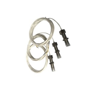
Power plant environments have significant electromagnetic interference from large motors, transformers, and variable frequency drives. The SMCB-01-10L60′s active signal conditioning gives it better interference rejection than a passive sensor, but the cable installation still matters. Signal cables should be routed away from power cables where possible, and the cable shield should be grounded at one end only — grounding both ends creates a ground loop that can introduce exactly the kind of noise the shield is supposed to prevent.
If erratic readings appear on a sensor that was previously working correctly, and the cable and sensor both check out fine, reviewing the grounding arrangement and cable routing for any recent changes to nearby power installations is worth doing before condemning the sensor or the monitor channel.
Summary
Abnormal readings from an SMCB-01-10L60 rotational speed sensor almost always trace back to one of four causes: power supply voltage, cable condition, the sensor itself, or the tachometer channel. Working through those in order — supply voltage first, then cable, then sensor output, then monitor channel — gives a clear path to the fault without replacing parts unnecessarily.
The sensor’s active design means you can measure meaningful diagnostic data in the field with a basic multimeter: supply voltage on the power wires, output signal behavior on the signal wire with the shaft rotating or a steel target passing the sensor face. Most faults either confirm themselves or rule themselves out within those two measurements.
Post time: Jul-14-2026
-

Reset solenoid valve MFZ3-90YC
-

Generator stator cooling water filter SGLQ-300A
-

A108-45 Mechanical seal of stator cooling water...
-

Servo valve SV4-20(15)57-80/40-10-S451
-

Industrial water filter KLS-100I plant Stator c...
-

Filter element MZFP-32-118 mesh
-

DP201EA01V-F actuator inlet flushing oil filter...
-

Stainless Steel Oil Level Meter DYW-250
-

Jacking oil pump filter element HBX-250×10
-

Differential pressure transmitter CS-III
-

Duplex oil filter element LX-FM1623H3XR
-

Booster pump oil throw sleeve HZB253-640-01-06