

A high-energy ignition system can produce a strong, reliable spark and still fail to light the burner consistently. When that happens, the first instinct is usually to check the ignitor unit, inspect the spark plug tip, or question the fuel supply. What often gets overlooked is something more basic: where exactly the ignition lance tip is sitting relative to the oil gun’s atomization cone.
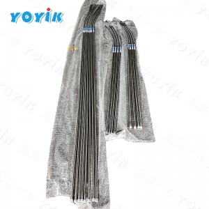
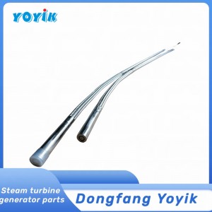
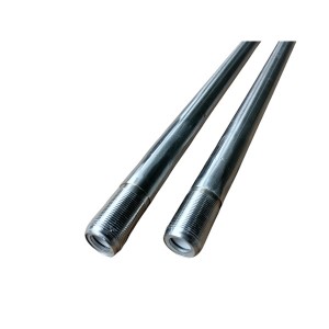
The JDQ-L2350 is a high-energy ignition lance designed for boiler startup ignition, industrial oil-fired furnaces, and gas boiler automatic ignition systems. It can directly ignite atomized diesel, heavy oil, and combustible gases. The spark plug tip has self-cleaning characteristics — resistant to fouling, coking, and moisture — and the spark energy output is substantial. All of that is useful, but it only delivers reliable ignition if the lance is positioned correctly and stays there.
Why the Tip Position Is the Critical Variable
When an oil gun atomizes fuel, the spray doesn’t ignite uniformly across the entire spray pattern. There’s a specific zone near the nozzle — the initial ignition kernel zone — where the fuel-air mixture is at the right concentration and velocity to be ignitable. Too far outside that zone and the mixture is either too lean, too rich, or moving too fast for a spark to initiate and sustain combustion.
The ignition lance tip needs to sit inside that zone. Not near it — inside it. The exact location varies depending on the oil gun nozzle design, the atomizing pressure, and the fuel type, but the general principle is consistent: the spark has to occur where the conditions for ignition actually exist.
If the JDQ-L2350 tip is positioned even a few centimeters off from the correct location, the spark fires into a zone where the mixture conditions are wrong. The spark energy may be perfectly adequate. The spark plug may be functioning exactly as designed. But the fuel-air conditions at that location don’t support ignition, and the light-off attempt fails. Operators see repeated ignition failures and start suspecting the ignitor hardware when the real problem is a positioning error that no amount of spark energy can compensate for.
The sensitivity to position is higher with heavy oil than with lighter fuels, because heavy oil atomization produces a less uniform spray pattern and the ignitable zone is narrower. On gas burners the ignitable zone tends to be wider, so position tolerance is somewhat more forgiving — but it still matters.
How to Establish the Correct Position During Installation
Getting the position right starts before the ignition lance goes anywhere near the burner. The oil gun manufacturer’s documentation specifies the recommended relationship between the ignition lance tip and the oil gun nozzle — typically expressed as a distance from the nozzle face and an angular offset from the spray centerline. These dimensions are the target to work from.
With the burner assembly accessible and the oil gun fitted in its operating position, the ignition lance is introduced through its mounting port and advanced until the tip reaches the specified location. A simple physical reference — a mark on the lance body at the point where it passes through the mounting fitting — lets the installer confirm the insertion depth consistently. Some installations use a mechanical stop or collar on the lance body to set the depth.
The angular position relative to the spray pattern also needs to be set correctly. Most burner designs have a defined mounting port orientation that puts the lance tip at the correct angular position when the lance is fully inserted to depth — but this assumes the mounting port itself is correctly positioned relative to the oil gun nozzle. On an installation where the port position isn’t well-documented, physically verifying the tip location relative to the nozzle before finalizing the mounting is worth the extra time.
If the plant has historically had inconsistent ignition success on a particular burner, and the ignitor hardware checks out, revisiting the tip position as-installed is a reasonable diagnostic step even on an existing installation.
Thermal Expansion and Vibration — Two Ways the Position Shifts After Installation
Getting the position right at cold installation doesn’t mean it stays right during operation. Two mechanisms work against it: thermal expansion and vibration.
Thermal Expansion
The furnace environment during burner operation reaches temperatures that cause measurable thermal expansion in all the metal components involved — the burner front plate, the oil gun assembly, the ignition lance itself, and the lance mounting hardware. Different components expand at different rates depending on their material and their distance from the heat source.
In practice this means the relative position between the lance tip and the oil gun nozzle can shift as the burner warms up from a cold start. The shift is usually small — a few millimeters — but in applications where the ignitable zone is narrow, a few millimeters is enough to affect ignition reliability. The shift is also repeatable: if thermal expansion moves the tip out of position on every startup, ignition difficulty will appear consistently at the start of each firing sequence and resolve as the tip position happens to move back during subsequent thermal cycling.
Accounting for thermal expansion means understanding the direction and magnitude of expected expansion in the installation-specific geometry, and intentionally setting the cold-installation position slightly offset to compensate. This is usually done based on experience with the specific burner design rather than detailed calculation, and the OEM documentation sometimes provides guidance on the cold-position offset to use.
Vibration
Power plant boiler burner fronts are vibrating structures during operation — combustion pressure pulsations, fuel and air flow turbulence, and adjacent rotating equipment all contribute. Over time, vibration works on any fastener or clamping arrangement that isn’t positive-locked, and the lance can work its way out of its set position.
The result is a gradual drift — the lance tip moves a small amount each firing cycle until the cumulative shift is enough to affect ignition reliability. This kind of failure is particularly frustrating because ignition was working fine for months and then starts becoming inconsistent without any obvious change having been made.
Making the Mounting Stay Put
The mounting arrangement for the JDQ-L2350 ignition lance needs to resist both thermal cycling and vibration over an extended service period. Several installation practices help with this:
- Use positive-locking fasteners. Standard nuts and bolts under vibration will loosen gradually. Lock nuts, spring washers, or thread-locking compound on the mounting hardware keeps the lance from shifting axially. Which method is appropriate depends on whether the fastener needs to be removed for maintenance access and how frequently.
- Clamp at two points if the lance length allows it. A single mounting point acts as a pivot — vibration causes the unsupported tip end to oscillate. Two clamping points constrain the full lance length and significantly reduce tip movement under vibration.
- Avoid rigid connections to thermally expanding structures. If the lance mounting bracket is attached to a component that expands significantly more than the lance body, the differential expansion will stress the mounting and potentially shift the lance. Flexible mounting arrangements or mounting to a thermally stable reference point reduce this.
- Mark the lance insertion depth visibly. A paint mark or reference line on the lance body at the mounting fitting shows immediately whether the lance has shifted axially since it was last set. Check it during routine burner inspections.
Installation Reference Summary
| Installation Factor | What to Do | Why It Matters |
|---|---|---|
| Tip insertion depth | Set per OEM specification; mark lance body at reference point | Positions tip in ignitable zone of atomization cone |
| Angular position | Verify tip location relative to nozzle before finalizing mount | Incorrect angle puts tip outside ignitable mixture zone |
| Cold-start offset | Apply OEM-specified compensation for thermal expansion direction | Thermal growth shifts tip position during warm-up |
| Fastener type | Use locking hardware — lock nuts, spring washers, or thread-lock | Prevents vibration from loosening the mount over time |
| Number of clamp points | Two points preferred for longer lance lengths | Reduces tip oscillation under combustion vibration |
| Mounting reference | Attach to thermally stable structure where possible | Differential thermal expansion stresses single-point mounts |
Checking Position During Routine Maintenance
Ignition lance position should be part of any routine burner maintenance inspection, not just something checked at initial installation. The check doesn’t have to be elaborate — confirm the insertion depth mark is still at the reference position, inspect the mounting hardware for any signs of loosening, and verify that the lance body hasn’t shifted laterally in its mounting bracket.
On units where ignition reliability has declined gradually, a position check before any hardware replacement is a sensible first step. A lance that’s drifted a centimeter or two from its set position can produce exactly the kind of intermittent ignition failure that looks like a spark plug problem or an ignitor unit issue. Repositioning and re-securing the lance costs nothing and might resolve the problem immediately.
The JDQ-L2350′s spark plug tip is designed to resist coking and fouling, which extends service intervals compared to standard ignition plugs. But that extended service life only translates to reliable ignition if the tip is in the right place. The best ignition lance hardware available won’t compensate for a positioning error.
If you’re sourcing JDQ-L2350 ignition lances for a new installation or replacing existing equipment, confirming the lance length against your burner geometry before ordering ensures the tip reaches the correct zone without modification. Installation documentation from your burner OEM is the reference to work from.
Summary
The ignition lance tip position relative to the oil gun atomization cone is the single most important installation variable for reliable boiler ignition. The JDQ-L2350 high-energy ignitor produces a strong, clean spark with self-cleaning characteristics — but that spark has to land in the right place. A positioning error of even a few centimeters can drop ignition success rate significantly, and the error often goes undiagnosed because attention goes to the spark hardware rather than the installation geometry.
Correct initial positioning, compensation for thermal expansion, and a mounting arrangement that resists vibration loosening are what keep the ignition lance working reliably across the full service life of the equipment. Get those three things right and the hardware will generally do what it’s designed to do.
Post time: Jul-14-2026
-

Low Resistance Anti-Corona varnish 130
-

Generator hydrogen cooling system safety valve ...
-

Steam turbine precision filter MSF-04S-03
-

Lubricating oil filter element LY-48/25W
-

977HP sealing oil differential pressure valve
-

Vacuum pump reducer gearbox M02225.013MVV1D1.5A
-

Online Hydrogen Leak Detector KQL1500
-

CWY-DO Steam Turbine Eddy Current Sensor
-

Generator stator cooling water filter SGLQ-1000A
-

Bellows relief valve BXF-40
-

AST/OPC solenoid valve coil 300AA00086A
-

High Pressure Welding Angle Globe Valve J64Y-64