

Getting overspeed protection right on a steam turbine is a balancing act. Trip too sensitive and you’re shutting down on false alarms, dealing with the mechanical stress of unnecessary trips, losing generation. Miss a real overspeed and the consequences are significantly worse. The speed monitor in the middle of that protection chain carries a lot of responsibility, and the QBJ-3C2/DO is built specifically for this job on steam turbine units.
What follows covers how the three-channel input works, what the voting logic actually does in practice, and how the monitor handles a situation where one sensor channel goes bad.
What It Does Day to Day
In normal operation the monitor just displays turbine rotating speed. That’s the baseline. But there’s a memory function running in the background that tracks the highest speed the unit has reached — stored and readable even after the turbine trips and restarts. That peak speed record is useful for incident investigation and for checking whether the protection system responded at the right point.
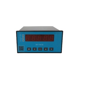
The memory function also captures what happens when the mechanical emergency governor fires. When the trip striker ejects, the monitor records the turbine speed at that exact moment. When the striker resets, that speed gets recorded too. Both values stay stored separately. So after a trip event, you can pull up the instrument and see exactly what speed the mechanical governor fired at and what speed it reset at — without needing a separate data logger or relying on operator memory.
For plants trying to verify that the mechanical governor is tripping within its calibrated range, this is genuinely handy. The data is right there in the monitor after the event, not buried in a historian system somewhere.
Why Three Sensor Inputs
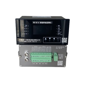
The QBJ-3C2/DO takes three independent speed sensor signals, each going to its own measurement channel inside the monitor. They all run in parallel, all independently tracking turbine rotating speed from separate probes on the shaft gear wheel.
Three isn’t an arbitrary number. It’s the minimum that makes meaningful voting logic possible. With two channels you can tell when they disagree, but you can’t tell which one is wrong. With three, if one reads differently from the other two, the majority tells you what the actual speed is and which channel is the outlier.
The sensors themselves are usually reluctance-type or proximity probes, mounted at different positions around the same target wheel. Each one is a physically independent sensor — not a single sensor signal split three ways. That matters because a cable fault, connector problem, or dead sensor only affects one channel and leaves the other two untouched.
The 2-of-3 Voting Logic
For overspeed trip decisions, the monitor uses 2-of-3 voting. A trip output only fires when at least two of the three channels independently see the turbine rotating speed exceed the trip setpoint. One channel reading high isn’t enough on its own.
This handles two failure scenarios that simpler arrangements can’t manage cleanly:
- False trip prevention: One sensor channel develops a fault and starts outputting a falsely high speed signal. The other two channels are still reading actual shaft speed. Voting sees one channel above setpoint, two below — no trip. The unit keeps running and a channel alarm fires so someone goes to investigate.
- Missed trip prevention: One sensor channel drops out or fails low. The two remaining channels can still detect a real overspeed event and agree on a trip. Protection still works with only two healthy channels.
A two-channel system can’t do both of these at the same time. If you require agreement between two channels to trip, then one failed-high sensor can block a genuine trip. If you trip on either channel independently, then one failed-high sensor causes false trips. Three channels with 2-of-3 logic is what actually solves both problems together.
When One Channel Goes Bad
The monitor watches the signal health on each input channel continuously. If a channel drops out — sensor dead, cable broken, signal out of range — the monitor flags it as faulted and generates a channel fault alarm. That faulted channel gets pulled out of the voting logic automatically.
The remaining two healthy channels keep running. Protection logic stays functional. The turbine doesn’t trip just because a sensor failed, and a real overspeed on the two good channels will still generate a trip output correctly.
The important thing here is that a channel fault alarm and an overspeed alarm are distinct. When one sensor fails, operators see a sensor fault on that channel — not an overspeed condition. That distinction matters. A monitor that can’t separate these two things creates confusion about what’s actually happening and tends to get operators ignoring alarms.
Running with one channel faulted does reduce redundancy. You’re effectively on two-channel protection now, and if a second channel fails the voting logic has nothing left to work with. A channel fault alarm should mean someone investigates and fixes it, not just acknowledges it and moves on.
Speed Setpoints and Alarm Levels
The QBJ-3C2/DO supports multiple configurable setpoints. For a typical steam turbine overspeed protection setup:
- High-speed alarm — usually around 103% to 105% of rated speed, early warning before anything protective needs to happen
- Overspeed trip setpoint — typically 110% to 112% of rated, where the monitor fires the trip output
- Zero-speed or low-speed threshold — used during startup and shutdown to confirm whether the shaft is actually rotating
For a standard 3000 rpm machine the setpoints are configured accordingly. The stored peak speed and emergency governor trip and reset speeds can all be compared against these setpoints when reviewing a trip event.
Functions at a Glance
| Function | What It Does |
|---|---|
| Speed display | Continuous real-time turbine rotating speed readout |
| Peak speed memory | Records and holds maximum speed reached since last reset |
| Emergency governor speed memory | Stores speed at striker ejection and retraction separately |
| Sensor inputs | Three independent speed sensor channels |
| Voting logic | 2-of-3 for overspeed trip decision |
| Channel fault handling | Faulted channel identified, removed from voting, alarm generated |
| Trip output | Fires when two or more channels confirm overspeed setpoint exceeded |
How It Fits Into the Wider Protection System
The monitor’s output connects to the turbine’s emergency trip system — either feeding the ETS logic or directly driving the solenoid valves that vent trip oil and close the main steam valves. The output type, contact rating, and wiring configuration need to match the rest of the protection system’s fail-safe design.
For turbines that still use a mechanical emergency governor alongside the electronic protection, the speed memory function gives a calibration data point during periodic overspeed trip testing. After a test, you can read the exact speed at which the mechanical governor fired and compare it against the specified range — without needing a separate speed recorder or oscilloscope on the probe signal. It’s a small thing but it simplifies the post-test paperwork.
If you’re looking at the QBJ-3C2/DO for a replacement installation, confirming sensor input compatibility — signal type, impedance, voltage range — against whatever probes are already mounted on the turbine is worth doing before placing an order. Speed sensor and monitor compatibility issues are easier to resolve before installation than during commissioning.
Testing and Maintenance Notes
Most plant maintenance programs include periodic testing of the overspeed protection channels. The monitor supports individual channel testing — each sensor input can be checked independently, which means you don’t have to take the full protection system offline to verify a single channel. You can confirm that each channel reads correctly and that the voting logic responds the right way to a simulated setpoint exceedance on each one individually.
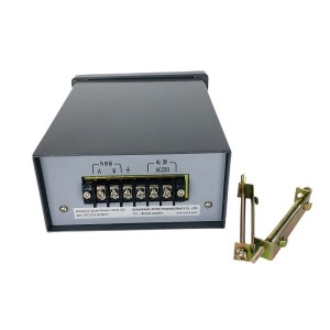
Peak speed memory and emergency governor speed records should be reviewed and documented after any trip event, then reset once the data is captured. Old values left sitting in memory without documentation become confusing if they get attributed to the wrong event later.
Channel fault alarms need a defined response time in the maintenance program. It’s easy to acknowledge them and defer the investigation, but operating with one faulted channel reduces the protection from three-channel to two-channel coverage. That’s still functional, but it’s reduced redundancy — and it stays reduced until the fault is fixed.
Bottom Line
The QBJ-3C2/DO handles turbine rotating speed monitoring, peak speed recording, mechanical governor trip speed capture, and three-channel overspeed protection with 2-of-3 voting logic in one instrument. A single failed sensor channel triggers a fault alarm and drops out of the voting logic automatically — it doesn’t cause a false trip, and it doesn’t leave the protection blind. The remaining two channels keep working.
For steam turbine applications where overspeed protection reliability and post-trip data matter, the combination of redundant inputs, defined voting behavior, and built-in speed memory covers the practical needs without requiring additional instrumentation around the monitor.
Post time: Jul-13-2026
-

Filter element MZFP-32-118 mesh
-

Generator end cap sealing Sealant SWG-1
-

BFPM hydraulic coupling oil filter DU631.3080.2...
-

Stainless steel globe throttle check valve LJC ...
-

Generator Epoxy adhesive DFCJ1306
-

Gas turbine cleaner ZOK-27
-

Generator end cap Sealant 53351JG
-

Generator Stator Cooling Water Filter MSL-125
-

Hydraulic oil station precision fine filter UE3...
-

COPALTITE High Temperature Sealant
-

Primary fan thin oil station Filter disc SPL-15
-

Insulation Alkali-Free Fiberglass tape ET60