

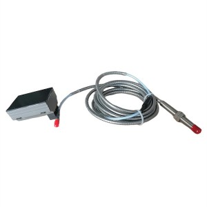
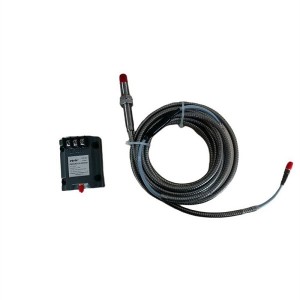
For industrial steam turbines, inaccurate differential expansion measurement is a serious concern. At best, it can lead to misjudgments in the control system and incorrect operating parameter adjustments. At worst, it can lead to undetected differential expansion between the rotor and cylinder, causing friction and potentially damaging the equipment. Eddy current sensors like the PR6423/010-140 are our primary tool for monitoring differential expansion. However, their measurement accuracy relies heavily on more than just the sensor itself; even minor installation errors can lead to erroneous data. Today, we’ll discuss the key elements of sensor installation: verticality, bracket rigidity, and foundation stability, and how to ensure these three key elements are met.
I. Why are differential expansion measurement and sensor installation so important?
During steam turbine operation, the rotor and cylinder expand at different rates and magnitudes due to their different heat-exposed locations and materials. This difference is called differential expansion. If the differential expansion exceeds a safe range, the rotor may rub against the cylinder wall, potentially causing component wear or, in severe cases, equipment failure.
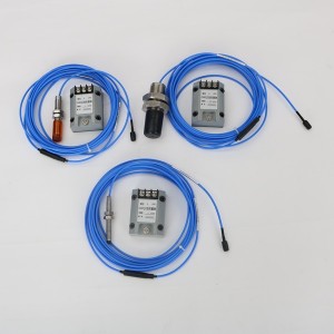
The PR6423/010-140 eddy-current sensor relies on non-contact measurement, measuring distance changes without touching the rotor. While its accuracy is inherently high, it places particularly stringent requirements on installation. I once encountered a situation where the sensor itself was fine, but the probe was slightly tilted during installation. This resulted in fluctuating differential expansion data. The maintenance staff initially suspected a problem with the equipment, but after considerable investigation, they discovered that the problem was installation misalignment. Therefore, installation quality directly determines whether the sensor can “tell the truth.”
II. Probe installation perpendicularity. Even the slightest deviation is unacceptable.
The operating principle of an eddy-current sensor is simple: as the distance between the probe and the metal surface being measured (such as a rotor) changes, the sensor’s output signal also changes. However, this requires a prerequisite: the probe must be perpendicular to the surface being measured. If it is tilted, the measured “distance” will not be the true perpendicular distance, resulting in errors.
For example, if the probe is tilted by 5 degrees, even if it appears to be “slightly tilted,” the final measured error can exceed 10%, far exceeding acceptable limits. Even more troublesome is that this error isn’t a “fixed deviation.” As the turbine rotor rotates during operation, the tilted eddy-current sensor probe will sense different signal strengths at different angles, causing constant fluctuations in data. During maintenance, it’s impossible to determine whether this is due to a true expansion differential or simply a tilted probe.
So how do you ensure verticality? Don’t rely on your gut feeling during installation; use a precision level to calibrate the probe. And don’t just calibrate once—perform a rough installation first, using a level to measure the angle between the probe and the axial axis. Once properly aligned, perform a fine adjustment to ensure the error is within ±0.5 degrees. Don’t rush to finish the installation either; recheck it again, especially when tightening the screws. It’s easy to accidentally tilt the probe, and a recheck can catch this problem early.
III. Insufficient bracket rigidity can cause vibrations to “trick” the sensor
Steam turbines vibrate during operation, which is unavoidable. However, if the bracket for the eddy-current sensor isn’t rigid enough, trouble can arise. If the bracket is soft, vibration will cause it to deform slightly, or even wobble slightly. The “distance change” measured by the sensor is actually the bracket’s movement, not a true change in the differential expansion between the rotor and cylinder.
In a previous case, a power plant used a thin-walled aluminum alloy bracket. While it appeared lightweight, vibrations caused the bracket to wobble slightly during operation. As a result, the differential expansion data measured by the sensor fluctuated between 0.05 and 0.2 mm, even though the actual change in differential expansion during normal operation was not that significant. Ultimately, investigation revealed that the bracket lacked rigidity. For the PR6423/010-140 eddy current sensor, this “false data” is more dangerous than no data at all, as it can easily lead the control system to make incorrect judgments.
When selecting a bracket, don’t prioritize cheapness or lightness. Prioritize high-strength materials such as stainless steel and alloy steel, and avoid overly thin structures. For example, the bracket arms must be sufficiently thick, and the connections must be secure. During installation, the bracket must be securely fastened to the turbine base, not just “hung” on top. The screws must be tightened to the specified torque to prevent loosening during operation. Simply put, the bracket must be “stable” and should not be moved easily even when vibration occurs.
IV. An Unstable Foundation Can Utilize All Previous Efforts in vain.
Even if the bracket and probe are installed correctly, all previous efforts may be wasted if the “foundation” upon which the eddy current sensor is mounted—that is, the foundation—is unstable. The “foundation” here refers to the turbine foundation or the ground to which the bracket is fixed. Any problems with it can cause the sensor’s measurement reference to be offset.
For example, foundation settlement—even just 0.1mm—can cause the sensor’s position to shift slightly, making the measured differential expansion inaccurate. Furthermore, foundation vibration—if the foundation itself is wobbly—can transmit this vibration to the bracket and probe, causing the sensor’s output signal to fluctuate and become unusable. Previously, an old power station had a slight foundation settlement due to age, but this was not addressed promptly. As a result, after the sensor was installed, the data consistently mismatched with the actual differential expansion. Ultimately, the problem was resolved by strengthening the foundation.
Thus, before installing the sensor, it’s crucial to inspect the foundation: check for cracks and obvious signs of settlement, and use a vibration meter to measure the vibration amplitude during operation. If the foundation is loose or has previously settled, it must be reinforced first—for example, by adding grouting and supports—to ensure the foundation is stable and stable, before installing the bracket and sensor. Furthermore, the bracket should not use flexible connections (such as rubber pads) but should be hard-connected to the foundation to prevent even small foundation movements from being amplified.
V. Key: These three points are not independent and must be addressed together.
At this point, some may ask: What if I ensure verticality but the bracket is a little flexible? The answer is no—these three points interact with each other.
For example, if the foundation vibrates slightly, if the bracket is rigid enough, the vibration won’t be transmitted to the probe, and the problem isn’t significant. However, if the bracket is flexible, the vibration will be amplified, causing the probe to wobble more. If the probe is also not mounted vertically, the measured distance errors will compound due to the vibration, making the final data completely unreliable. Only when all three criteria are met can the PR6423/010-140 eddy current sensor output stable and accurate data; any one of them will be insufficient.
VI. Practical Advice for Operations and Maintenance: Don’t Skip These Steps
Finally, here are a few details you can use during actual installation to help you avoid mistakes:
Don’t skimp on vertical calibration: Use a precision level with a 0.02mm accuracy to measure the probe in all four directions, ensuring the verticality error is within ±0.5 degrees in each direction. After installation, don’t rush to power on the power cord. Use a feeler gauge to re-measure the gap between the probe and the surface being measured to ensure it’s evenly spaced. If the gap is larger on one side than on the other, it indicates it’s still skewed.
Don’t make do with the bracket: Choose a stainless steel bracket with a thickness of at least 5mm. The bracket arms should be short, as longer ones increase the risk of wobbling. If the installation location is near a vibration source, you can add small reinforcing ribs to the bracket to increase rigidity. Use locknuts to secure the bracket screws to prevent loosening during operation.
Before installation, check the base surface for flatness and to see if there’s any oil or debris that could affect the bracket’s fit. Use a spirit level to check the levelness of the foundation, then use a vibration meter to measure the foundation vibration during operation, ensuring the amplitude does not exceed 0.01mm. If it exceeds this, reinforce the foundation before installing the sensor.
After installation, power on the unit and first measure the signal output under static clearance to verify stability. Then simulate slight rotor movement (for example, using a dedicated tool to fine-tune the probe position) to verify the linearity of the signal change. Finally, run the unit at idle for half an hour and observe any fluctuations in the data. If fluctuations exceed 0.02mm, recheck the installation.
VII. Don’t Ignore: Installation Errors Can Have Significant Consequences
Some may think a 0.1mm error isn’t a big deal, but for steam turbines, even a 0.1mm error in the eddy current sensor PR6423/010-140 can cause problems. For example, during turbine startup, if the sensor doesn’t accurately measure the differential expansion, believing the rotor expansion is insufficient, and failing to adjust the inlet steam temperature in time, this can cause the rotor and cylinder to “seize.” During operation, if the differential expansion is mistakenly determined to be excessive, a protective shutdown can be triggered, delaying production.
Actually, getting accurate measurements with the PR6423/010-140 sensor isn’t difficult. The key lies in carefully considering these three installation details: proper verticality, a sturdy bracket, and a stable foundation. Post-installation testing, meanwhile, essentially guarantees reliable data. In the field of operations and maintenance, sometimes it’s not the complexity of the technology that matters, but the ability to pay close attention to detail, wouldn’t you agree?
If anyone has encountered special circumstances when installing this sensor, such as adjusting verticality in a confined space or selecting a bracket for locations with high vibration, we welcome your feedback. After all, sharing practical experience can help everyone avoid pitfalls.
When looking for high-quality, reliable eddy current sensors, YOYIK is undoubtedly a choice worth considering. The company specializes in providing a variety of power equipment including steam turbine accessories, and has won wide acclaim for its high-quality products and services. For more information or inquiries, please contact the customer service below:
E-mail: sales@yoyik.com
Tel: +86-838-2226655
Whatsapp: +86-13618105229
Yoyik offers various types of power plants spare parts for steam turbines, generators, boilers as below:
Armored Thermocouple TE-202
Speed Transducer CS-01
Ignition gun EHE-20-B-1-18S
Armoured Wear Resistant Thermocouple WZGPK2-73 SC PH 00
Monolithic pilot light XB2BVQ4LC
Linear LVDT Sensor HTACC-LT-607Z
Eddy Current Sensor PR6422/101-000
intelligence Hand Operator NPDF-Q110F4
Acoustic conduit DZXL-ⅢB1
HP CASE EXPANSION SENSOR TD-2
industrial pressure transmitter ST307-V2-150B
CV LVDT Sensor 2000TD 0-100 MM
Eddy Current Sensor PR6422/105-141
Objective lens front end YF-A18-5A-2-0/B
PHASE-MISSING PROTECTION MODULE WK-2 CN0504
PROXIMITY SENSOR VMS808-21-50-00-00
Quick fuse 170M6501
position sensor types TDZ-1-11
Multifunctional electric instrument PD194AE-254G
Fuse XRNP
sight glass gauge DQS-76
Speed digital display instrument MCS-II-3
ROTATIONAL SPEED SENSOR CS-1-L120
Key phase sensor CS-1 D-100-02-01
LVDT Position sensor C9231129
Magnetoresistive speed sensor CS-1-G-055-05-01
LVDT Sensor TDZ-1C-03
intelligence Hand Operator NPDF-Q211D4
Post time: Sep-16-2025
-

Hydraulic oil filter element LX-HXR25X20
-

EH oil main pump working filter element AP3E301...
-

Regeneration device cation filter PA810-001D
-

Active/Reactive Power (Watt/ Var) Transducer S3...
-

Magnetic reed switch (sensor) CS1-F
-

Boiler Tube sliding block
-

High Energy Igniter Spark Rod XDZ-F-2990
-

DF9011 Pro Precision Transient Rotational Speed...
-

Generator stator RTV epoxy adhesive J0708
-

GJCF-15 APH Gap Control system Signal Transmitter
-

Steam Turbine Shutoff Valve HGPCV-02-B30
-

Lubricating oil filter element 21FC5128-160X600/25