

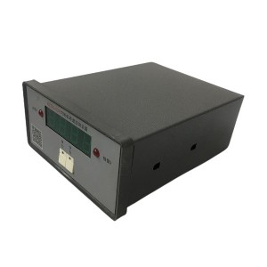
The ZKZ-3T is a multi-purpose speed monitor that combines the functions of a frequency meter, tachometer, speed relay, and speed test instrument in a single panel-mounted device. It is designed for continuous speed monitoring of hydro turbine generator units, providing both digital display and switching outputs at configurable speed setpoints, with analogue output tracking actual shaft speed in real time.
Measurement Principle: Why Variable Gate Period Counting Matters
Many speed measurement instruments use a fixed time gate — they count pulses from a speed sensor over a fixed interval, say one second, and calculate speed from the count. At low shaft speeds, that fixed gate produces coarse resolution: if the unit is turning at 5 rpm and the sensor produces, say, 60 pulses per revolution, only five pulses arrive per second. The reading updates slowly and jumps in steps rather than tracking smoothly.
The ZKZ-3T uses a variable gate, period-counting approach instead. Rather than counting pulses over a fixed time window, it measures the time between consecutive pulses from the speed sensor. Speed is derived from that period — the reciprocal of the pulse interval, scaled to rpm. As shaft speed increases, pulse intervals become shorter and the measurement updates more frequently. At low speeds, each individual pulse still provides a discrete speed estimate the moment it arrives.
The practical result is better real-time responsiveness and accuracy at the speed ranges that matter most for hydro turbine monitoring — particularly during startup, runup, and the low-speed ranges where creep detection operates. Because the accuracy of this approach depends on the precision of the internal crystal oscillator used to time the pulse intervals, not on counting resolution, the measurement does not drift with temperature or ageing. Setpoint contact outputs remain stable across years of operation without periodic recalibration.
Signal Inputs and System Integration
The ZKZ-3T accepts speed pulse signals from external speed sensors — typically magnetic pickup transducers mounted at the turbine shaft or gear teeth — and voltage signals from a voltage transformer (VT) connected to the generator terminals. The dual-input arrangement allows cross-checking between the mechanical pulse signal and the electrical frequency signal, which is directly proportional to shaft speed in a synchronous generator.
Outputs from the device serve multiple downstream functions:
- Switching (relay) outputs: Configurable setpoints for startup permission speed, synchronisation speed, overspeed alarm, and overspeed trip. Each setpoint triggers a relay contact output used by the plant control system or protection logic.
- Analogue output: A 4–20 mA or 0–10V signal proportional to shaft speed, routed to the plant SCADA or DCS for continuous speed trending and historical logging.
- Panel display: Real-time digital readout of shaft speed in rpm and frequency in Hz, updated continuously from the variable gate measurement.
For automatic start and stop sequences on hydro turbine generator units, the ZKZ-3T switching outputs gate the critical transitions — governor enable at a defined minimum speed, synchronisation window at near-synchronous speed, and trip confirmation above the overspeed setpoint. The stability of these setpoints, backed by crystal oscillator accuracy rather than analogue component drift, is one of the device’s operational advantages in long-running installations.
Creep Detection: The Function That Causes the Most Commissioning Problems
Hydro turbine units in shutdown state are supposed to be stationary. In practice, that is not always the case. Water flowing past closed guide vanes, turbulence in the draft tube, pressure pulsations in the penstock, or slight guide vane leakage all generate small forces on the runner. On units with kaplan (adjustable blade) runners, the blades themselves can oscillate slightly in response to hydraulic pressure variation even when nominally closed.
The creep detection function in the ZKZ-3T monitors whether the shaft is rotating — even very slowly — when it should be stopped. If shaft movement is detected above a defined threshold, the device generates a creep alarm or, depending on how the protection logic is configured, can initiate an emergency stop sequence to engage the mechanical brake.

The problem is that very small oscillatory movement of the guide vanes or blades in response to turbulent flow past them can produce intermittent pulses at the speed sensor — not true rotation, but vibration that looks like rotation to a pulse-counting device. If the creep detection threshold is set too sensitively, or if the time delay before alarm is too short, these hydraulic-driven oscillations trigger false alarms at shutdown. In severe cases, the false alarm cascades into an automatic stop sequence that engages the brakes on a unit that isn’t actually rotating — unnecessary wear, unnecessary operator response, and in some designs, a mechanical sequence that takes time to reverse before the unit can be restarted.
Adjusting Creep Parameters to Match Site Conditions
The ZKZ-3T provides adjustable parameters for creep detection: the speed threshold (the minimum pulse frequency interpreted as “rotation”) and the time delay before the alarm output activates. Getting these two values right for a specific installation requires understanding what the sensor is actually seeing when the unit is at rest.
Step 1: Characterise the At-Rest Signal
Before adjusting any parameter, log the raw speed sensor signal when the unit is confirmed stationary — brakes applied, guide vanes fully closed, no intentional movement. If the ZKZ-3T or an external logger can record the pulse frequency at the sensor input during this condition, the data shows the noise floor: the rate of spurious pulses generated by mechanical vibration, hydraulic pressure oscillation, or electrical interference in the sensor circuit when there is genuinely no shaft rotation.
The creep action threshold must be set above this noise floor, with enough margin that normal hydraulic-induced vibration at rest does not cross it. If the noise floor under worst-case flow conditions — high headwater, turbulent inflow, or penstock pressure pulsation during adjacent unit operation — produces an apparent speed signal of, say, 0.3% of rated speed, the creep threshold should be set meaningfully above that value, not at 0.1%.
Step 2: Set the Time Delay to Filter Out Transient Events
Guide vane or blade vibration in response to water turbulence is typically intermittent and non-sustained. A pulse burst from a momentary vibration event lasts a fraction of a second — the guide vane deflects slightly and returns. True shaft rotation, even slow creep, produces a sustained and consistent pulse stream.
The time delay parameter in the ZKZ-3T creep function determines how long the speed signal must exceed the threshold continuously before the alarm output activates. A short delay — under one second — will trigger on momentary vibration events. A delay of three to five seconds filters out most transient hydraulic disturbances while still catching genuine slow rotation that persists.
The appropriate delay depends on the typical duration of hydraulic disturbance pulses at that specific site. A station with known penstock pressure oscillations from upstream valve operations may need a longer delay than one with stable hydraulic conditions at shutdown. The only way to calibrate this correctly is to observe the actual pulse pattern during shutdown conditions and set the delay to exceed the longest observed transient duration by a reasonable margin.
Step 3: Test the Adjusted Settings Systematically
After adjusting the threshold and delay, verify both directions of the sensitivity trade-off before declaring the settings final:
- Confirm no false alarm is generated during a representative shutdown period, including periods of active water flow past the closed guide vanes and any conditions known to produce hydraulic disturbances (e.g., adjacent unit startup or load changes).
- Confirm the device detects intentional very slow rotation — using barring gear or manual rotation of the shaft — at a speed that represents genuine creep, to verify that the threshold is not so high that real slow movement is ignored.
Document the final setpoint values and the conditions under which they were validated. If hydraulic conditions at the site change — new penstock modifications, changes to adjacent unit operation, or turbine runner replacement — the characterisation and adjustment process should be repeated.
Speed Setpoint Reference Table
| Setpoint Function | Typical Range (% of rated speed) | Purpose in Unit Control |
|---|---|---|
| Creep detection threshold | 0.5% – 3% (site-specific) | Detect shaft rotation when unit should be stationary; triggers brake engagement or alarm |
| Brake release speed | 5% – 15% | Minimum speed at which mechanical brakes are confirmed released during startup runup |
| Governor enable speed | 20% – 40% | Speed at which the governor begins active control; below this the guide vane is on manual or fixed opening |
| Excitation enable speed | 80% – 95% | Minimum speed for applying field excitation to the generator; below this the residual voltage is too low for AVR control |
| Synchronisation window | 98% – 102% | Speed band within which synchronisation to the grid is permitted; breaker close inhibited outside this range |
| Overspeed alarm | 105% – 110% | First-stage overspeed; triggers alarm and governor intervention |
| Overspeed trip | 115% – 140% | Hard trip setpoint; initiates emergency guide vane closure and unit trip regardless of other conditions |
Actual setpoint values for a specific installation are determined by the turbine OEM specification, the generator protection study, and the plant’s operating procedures. The ranges above are typical for kaplan and Francis turbine units and should not be applied without reference to the unit-specific design documents.
Long-Term Stability and Maintenance Considerations
One of the operational advantages of the ZKZ-3T’s crystal oscillator-based measurement is that the speed contact setpoints do not drift over time the way analogue relay-based systems do. A setpoint programmed at commissioning remains accurate as long as the crystal oscillator is functioning within specification — its frequency error is on the order of parts per million, stable across the temperature range of a typical control panel environment.
Maintenance requirements for the device itself are minimal: periodic functional verification that each relay output activates at the configured setpoint, and inspection of the signal cable connections from the speed sensor and voltage transformer, which are more prone to degradation than the device electronics. The speed sensor itself — typically a magnetic pickup or proximity sensor at the turbine shaft — warrants separate inspection for mounting security, air gap setting, and cable condition, as sensor signal quality directly affects the accuracy of the speed measurement and the reliability of the creep detection function.
E-mail: sales@yoyik.com
Tel: +86-838-2226655
Whatsapp: +86-13618105229
Yoyik offers various types of power plants spare parts for steam turbines, generators, boilers as below:
key phase amplifier TM0180-A07-B00-C05-D50
Sensor RTD 6uide Bearing Generator Pad L 1685mm x Dia 129mm
intelligence Hand Operator NPDF-D110FD4
Transmitter level meter 704-511A-140/7MA-A110-130
lvdt sensor price DET-20A
Main steam valve oil motor displacement LVDT CCH02A.302Z
24 volt proximity sensor CWY-DO-810030-040-01
Human Interface Module 20-HIM-A6
Power unit FDPC75C3-B
Speed Sensor T-03
Eddy Current Sensor PR6422/101-041
Isolated barrier GS8036-EX
rpm pickup DF6101-005-065-01-05-00-00
intelligence Hand Operator NPDF-Q11F4
Advanced Battery Analyzer BT521
Eddy Current Signal Converter CON011/914-060
Pressure Switch 4NN-K5-M4-C2A
temperature sensor WZP2-005
Eddy Current Sensor PR6423/002-121
Post time: Jun-01-2026
-

DWQZ series proximitor Axial displacement Eddy ...
-

DP201EA01V-F actuator inlet flushing oil filter...
-

lubricating oil filter element 2-5685-0154-99
-

Differential Pressure Switch CMS
-

Recycle pump working filter DP1A401EA03V/-W
-

China manufacturer Honeycomb Filter SS-C05S50N
-

AST/OPC solenoid valve SV4-10V-C-0-00
-

Generator stator cooling water filter WFF-150-1
-

Jacking Oil System Backwash Filter ZCL-I-450
-

Linear variable displacement transducer LVDT se...
-

AST solenoid valve GS021600V
-

Stainless Steel Oil Level Meter DYW-250