

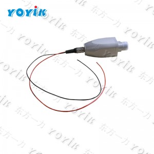
The KQF1500 is an online gas leakage detection transmitter for hydrogen-cooled generators, built around thermal conductivity sensing to continuously monitor hydrogen concentration inside the generator casing. It sends a 4–20 mA signal to the DCS and activates relay alarm contacts when concentration falls outside acceptable limits. The harder problem — and the one that matters more in day-to-day operation — is deciding whether an alarm reflects a real hydrogen leak or a transmitter issue.
How Thermal Conductivity Detection Works
Hydrogen has a thermal conductivity roughly seven times higher than air. The KQF1500 exploits this difference by passing the sampled gas mixture over a heated sensing element. When the gas composition changes — specifically when hydrogen concentration drops because air or other gases have diluted it — the rate of heat transfer from the element changes, and the element’s temperature shifts. That temperature change, measured as a resistance change in the sensing circuit, is the basis of the concentration reading.
This approach is continuous and passive — no chemical reaction, no consumable reagent. The sensor’s output tracks concentration changes in real time as long as gas flow through the sampling path is maintained. The 24VDC supply from the secondary instrument powers both the sensor heating element and the signal conditioning circuitry.
The measurement is sensitive to anything that changes the thermal conductivity of the sampled gas, not just hydrogen. Water vapour content, gas temperature, and the presence of other gases all influence the reading to varying degrees. This is the root of both the false alarm and missed alarm problems — conditions that change the gas composition without actually representing a hydrogen leak can shift the transmitter output in ways that look like concentration changes.
What the KQF1500 Monitors and Where It Sits in the System
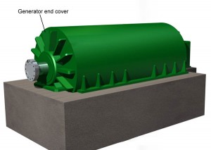
The transmitter is installed to sample gas from inside the generator casing — typically from the hydrogen supply and return circuit, or from a dedicated sampling point at the generator end covers. In a healthy, sealed generator at rated hydrogen pressure, the internal atmosphere is essentially pure hydrogen with controlled humidity. The transmitter should be reading near 100% hydrogen purity under these conditions.
A reading that drops toward lower purity indicates one of three things: hydrogen is escaping and being replaced by air ingress, air or another contaminant gas has been introduced, or the transmitter itself is reading erroneously. Distinguishing between these three requires more than the transmitter output alone.
The 4–20 mA signal maps to a concentration range — typically 0% to 100% hydrogen purity, or in some configurations 0% to the lower explosive limit for safety monitoring at locations outside the casing. The DCS receives this signal continuously and triggers alarm outputs based on configurable threshold values set during commissioning.
Sources of False and Missed Alarms
False alarms from a gas leakage transmitter in generator service tend to come from a small number of recurring causes. Understanding them is the starting point for reducing nuisance trips without reducing actual protective sensitivity.
Sensor Drift
Thermal conductivity sensors drift over time. The sensing element ages, reference gas composition in the comparison cell changes slightly, or contamination on the element surface alters its heat transfer characteristics. A transmitter that was zeroed and spanned at commissioning may show a different output for the same actual gas composition two years later. That drift is slow — it won’t produce a sudden alarm — but it can cause the baseline reading to sit 1–3% away from true value, which narrows the margin to alarm setpoints.
Regular calibration against a reference gas of known composition is the only way to catch drift before it becomes a problem. Most maintenance programmes for this type of gas leakage transmitter specify calibration at six to twelve month intervals.
Humidity Effects
Hydrogen inside the generator is maintained at controlled humidity — too dry causes static discharge risk, too wet causes condensation in the windings. Changes in hydrogen moisture content affect the thermal conductivity of the sampled gas and therefore affect the transmitter reading. If the hydrogen dryer in the sealing oil system is underperforming, or if the humidity control system has drifted, the KQF1500 may show a concentration shift that is actually a humidity effect rather than a purity change.
Sampling Path Issues
A blocked or partially restricted sampling line reduces gas flow past the sensor. The sensor may then read the stagnant gas composition in the sampling tube — which can be different from the bulk generator atmosphere, particularly if the sampling point is in a location prone to localised condensation or if the line has developed an air pocket. A sudden alarm following a period of stable readings, with no other corroborating evidence of leakage, should prompt a check of sampling line condition before assuming the generator has developed a leak.
When the Alarm Activates: The Diagnosis Process
An alarm from the KQF1500 gas leakage transmitter is the beginning of a structured assessment, not an immediate emergency response on its own. The transmitter has confirmed that something has changed in the sampled gas composition. What that change means for the generator’s actual condition depends on what the other monitoring systems are showing at the same time.
Daily Hydrogen Make-Up Volume
Every hydrogen-cooled generator consumes a small, consistent volume of hydrogen each day through normal permeation and minor seal leakage — this is the baseline make-up volume. Operators or the DCS trend system log the volume of hydrogen supplied to the generator each day to maintain rated pressure. If the transmitter alarm is accompanied by a measurable increase in daily make-up volume above the established baseline, the two indicators together are a much stronger signal of actual leakage than either one alone.
An alarm with no change in daily make-up volume is a significant clue. A real hydrogen leak large enough to shift the transmitter reading by 2–3% purity would require a noticeable increase in the hydrogen replenishment rate. If the make-up volume is unchanged, the transmitter itself is a more likely explanation for the alarm.
Hydrogen Humidity Inside the Generator
The hydrogen humidity reading from the generator’s moisture monitor should be checked immediately after a concentration alarm. If humidity has risen sharply alongside the purity drop, water vapour is entering the system — possibly through a failed seal or a cooling water leak — and affecting both readings simultaneously. If humidity is stable and within normal range, a humidity-driven false alarm from the gas leakage transmitter is less likely.
Stator Bar and Stator Cooling Water Temperature
In water-cooled stator winding designs, cooling water circulates through hollow conductors inside the stator bars. A leak in the stator cooling water system introduces water directly into the generator atmosphere. The temperature differential between the stator bar surface temperature and the stator cooling water inlet temperature will shift if flow is reduced by a leak. Combined with a hydrogen purity drop, elevated stator bar temperature points toward a cooling water leak rather than a gas-side seal failure.
Hydrogen Content in Stator Cooling Water
Many large generators include a dissolved hydrogen analyser on the stator cooling water circuit. If hydrogen is leaking into the water circuit — through a failed stator bar conductor insulation — the dissolved hydrogen content in the cooling water increases measurably. A simultaneous alarm on the KQF1500 gas leakage transmitter and a rising dissolved hydrogen reading in the cooling water is a strong combined indicator of stator conductor leakage, which is a different failure mode and different urgency level than a shaft seal leak.
Drain Tank Liquid Level
The generator casing drain or hydrogen-side detraining tank collects any liquid that accumulates in the generator atmosphere — condensation, seal oil carryover, or cooling water from a leak. An unexplained rise in liquid level in the drain tank, coinciding with a hydrogen purity alarm, suggests liquid ingress into the generator that would also affect the sampled gas composition at the transmitter. This is one of the more definitive corroborating indicators of a real leak rather than a transmitter fault.
Decision Matrix: Transmitter Fault vs Real Leakage
| KQF1500 Reading | Supporting Indicators | Most Likely Assessment |
|---|---|---|
| Purity alarm; reading dropping slowly over hours | Daily H₂ make-up volume increasing; drain tank level rising; humidity stable | Real leakage likely. Check shaft seals and end cover joints. Increase monitoring frequency. Do not reset alarm without investigation. |
| Purity alarm; reading drops then stabilises | H₂ make-up volume unchanged; humidity stable; drain tank level normal | Transmitter drift or sampling path issue more likely. Check calibration against reference gas. Inspect sampling line for blockage or air pocket. |
| Purity alarm; humidity rising simultaneously | Stator cooling water temperature differential increased; dissolved H₂ in cooling water elevated | Cooling water ingress into generator atmosphere. Stator cooling water circuit requires immediate attention. Different failure mode from gas seal leakage. |
| Sudden sharp purity drop then recovery | No change in any other indicators; sampling line recently disturbed or maintenance performed nearby | Likely sampling path disturbance or brief air ingress during nearby work. Check sampling line integrity. Single event without recurrence can be logged and monitored. |
| Gradual purity reading decline over weeks; no acute alarm | H₂ make-up volume at upper end of normal but not clearly elevated; no other indicators | Early stage slow leak or sensor drift. Cross-reference with portable H₂ detector at known seal locations. Calibrate transmitter against reference gas before drawing conclusions. |
Avoiding Missed Alarms: What Desensitises the KQF1500
Missed alarms — where the transmitter fails to respond to an actual leak — are less common than false alarms but more consequential. The main causes are sensor contamination, calibration drift that has shifted the reading high (making the transmitter optimistic about purity), and sampling path blockage that isolates the sensor from the bulk generator atmosphere.
A transmitter that has not been calibrated in over a year, and has not shown any alarms during that period, is not necessarily performing correctly. Sensor drift that raises the apparent reading means an actual purity drop may not reach the alarm threshold when the uncorrected reading is already 2–3% above true value. The calibration record is the only way to confirm the transmitter is reading correctly, not just reading consistently.
Sampling line blockage is insidious for the same reason — a blocked line means the sensor reads whatever gas was last present, indefinitely. If the blockage occurred when the generator was in good condition, the sensor will continue reading good purity regardless of what is actually inside the casing. Verifying gas flow through the sampling path at each calibration visit is a simple check that catches this before it becomes a missed alarm event.
Installation and Power Supply Notes
The KQF1500 requires a stable 24VDC supply from the secondary display instrument. Voltage fluctuations in the supply directly affect the heating current to the thermal conductivity sensing element, which shifts the measurement baseline. In installations where the 24VDC supply is shared with other instruments on a common rail, load-induced supply variations can introduce measurement noise. Dedicated power supply circuits for the transmitter and its secondary instrument, or installation of a local voltage regulator, reduce this interference source.
Grounding of the signal cable shield is the other installation point that most frequently causes measurement noise in field practice. The 4–20 mA signal is low-level and susceptible to interference from nearby high-current equipment — particularly in generator terminal areas. Single-point grounding of the shield at the DCS end, with the transmitter end floating, is the standard practice for this type of measurement loop.
E-mail: sales@yoyik.com
Tel: +86-838-2226655
Whatsapp: +86-13618105229
Yoyik offers various types of power plants spare parts for steam turbines, generators, boilers as below:
Displacement Sensors 1000TDG-10-01-01
Travel switch ZV7H236-11Z
Pressure Switch BH-603002-603
thermal resistance WZP-440K
Eddy Current Sensor PR6422/102-021
Transformer medium voltage bushing terminal BJW-40/2000
safety pressure switch YWK-50-C
Swelling indicator HPSQ550×150-150
high temp thermocouple wire type k WRNK2-294
Eddy current sensor extension cable DS821.ec100/40/0
Position Monitor DM-4
Stainless Manometer YJFT-100
oil pressure solenoid RC861CJ091JYM
bolts heater 1.2311(4)-φ24.5X800(R)
Displacement Sensors C9231019
Flow Switch LKB-01B
contactless position sensor TDZ-1E-33
magnetic induction bolt heater RJ-17.5-1050
Eddy Current Sensor PR6423/001-030
Pressure Controller Inteligence Display QYJ-10-Kpa
Temperature Controller P-300A
bolts heater 1.2311(4)-φ36X1500
Post time: Jun-01-2026
-

Generator slot Sealant 730-C
-

Servo Manifold Spray HP Bypass Oil Filter C6004...
-

ZB2-BE101C handle selector push button Option s...
-

OPC solenoid valve 4WE6D62/EG220N9K4/V
-

DF6101 Steam turbine magnetic rotation speed se...
-

Electrohydraulic converter oil filter element S...
-

Accumulator Rubber Bladder NXQ-A-25/31.5
-

Hydraulic oil Pump Filter Element SDGLQ-25T-32
-

EH oil-return filter DL006001
-

Filter for EH oil station DL008001
-

Single Channel Speed Monitor D521.02
-

LVDT Position Sensor TD-1 0-100