

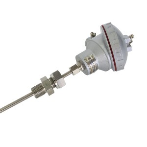
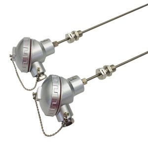
The WRNK2-321 is a dual-element K-type armored thermocouple with an adjustable compression fitting for threaded process connections. Both thermocouple elements share one sheath but operate independently — giving you a backup reading from the same point without pulling a second assembly through the same thermowell. The part that installation guides tend to gloss over is how fragile the internal insulation is once bending begins.
Construction and What “Armored” Actually Means
Strip the outer sheath from any armored thermocouple and you find three things: the thermocouple wires themselves, compacted magnesium oxide powder packed tightly around them, and a seamless metallic tube holding everything together. The sheath is typically stainless steel, though Inconel variants exist for higher temperature ranges. This combination — sometimes called mineral insulated or MI construction in international standards — is what distinguishes armored thermocouples from the wire-in-tube protection-tube type.
The MgO does two jobs at once. It holds the wires centred inside the sheath so they don’t touch each other or the sheath wall, and it provides the electrical insulation that keeps the thermocouple signal clean. The sheath can be bent because the compacted MgO redistributes under gentle, controlled flexing. That redistribution has limits.
Inside the WRNK2-321, there are two complete K-type circuits — two pairs of conductors, each with its own hot junction, embedded in the same MgO fill and sharing the same sheath. Both terminate at the connection head, feeding separate transmitter inputs or measurement channels. For any measurement point where a single-element failure would be operationally problematic, this dual arrangement means a fault in one element doesn’t force an immediate instrument replacement.
The Adjustable Compression Fitting
The “WRNK2″ designation tells you the mounting style: a movable compression fitting rather than a fixed flange or welded connection. It consists of a threaded body that screws into the process connection or thermowell, a ferrule that grips the sheath when compressed, and a locknut that locks everything in place once the insertion depth is set.
The practical benefit is on-site adjustability. After the fitting body is installed in the process connection, the sheath slides through the ferrule freely. Position the measuring tip where it needs to be, then tighten the locknut. The ferrule compresses against the sheath, fixing the depth and sealing the process connection in one action. The same physical assembly can accommodate different insertion depths without cutting a custom-length sheath.
The seal is the ferrule. Properly compressed, it prevents process fluid from working back along the sheath toward the connection head. Under-tighten it and you have a leak path. Over-tighten it and you deform the sheath wall locally — which is a different kind of problem, covered below.
Why Bending Radius Is Not a Guideline — It’s a Limit
The sheath can be bent. That’s one of the genuine advantages of armored over rigid protection-tube thermocouples, and in congested installations it matters. But the internal consequence of a bend that’s too tight isn’t visible from outside — the sheath surface stays smooth and the overall shape looks fine while something has already broken inside.
When the sheath bends, the MgO on the inside of the curve is compressed and the particles on the outside separate slightly. Within the minimum bend radius the manufacturer specifies, the fill redistributes without fracturing. Go tighter than that, and the compacted powder cm racks. The wire conductors — which were centred and supported — lose that support at the bend location and may shift position.
Most sheath specifications express the minimum bend radius as a multiple of the outer diameter: typically 5× to 10× OD, depending on sheath material and temperature at the time of bending. For a 6mm OD sheath, that’s a minimum radius of 30–60mm. In a tight cable tray or a cramped instrument cabinet, it’s easy to go tighter than that without noticing.
What Happens When MgO Insulation Is Damaged
Magnesium oxide absorbs moisture. In an undamaged sheath, the MgO moisture content is controlled at manufacture and the sheath ends are sealed. Once the MgO cracks from overbending, that seal is compromised internally — not at the end cap, but along the length where the fracture runs. Two failure paths open up from there.
Insulation Resistance Degradation
Moisture migrating into the cracked fill reduces the electrical resistance between the conductors and the sheath. As that resistance falls, leakage current begins flowing in parallel with the thermocouple signal. The measurement circuit can’t separate the two. The temperature reading drifts — usually toward ambient — and becomes increasingly erratic as moisture content rises.
Below around 100 MΩ at ambient temperature, moisture contamination in the MgO is likely. Below 1 MΩ, the reading is no longer reliable for anything that matters. The frustrating thing about bend-induced damage is that the insulation resistance may still read acceptable immediately after installation. The degradation accelerates only once the assembly is exposed to humidity, steam, or thermal cycling — which drives moisture progressively deeper into the cracked fill.
Wire Conductor Damage and Open Circuits
Where the bend radius is severely exceeded — where the sheath has been kinked rather than bent — the MgO can fracture completely enough to physically damage the conductors. The wires inside an armored thermocouple sheath are fine: typically 0.3mm to 0.8mm diameter. They rely entirely on the surrounding MgO for mechanical support. If the MgO collapses at a kink, the wire bends unsupported at that point and may break immediately or fatigue progressively under vibration.
Vibration-induced failures from a kinked sheath often appear weeks or months after installation. The wire hasn’t broken yet when the thermocouple is first put in service — it fractures later, after enough flexing cycles accumulate at the stress concentration point. When the open-circuit fault finally shows as an over-range reading, the kink made at installation isn’t always the first place people look.
Installation Practices That Prevent These Problems
Bending flexibility is a feature worth preserving, not exploiting carelessly. These practices stop most of the damage modes above before they start:
- Bend before tightening the fitting: All routing bends should be complete before the compression ferrule is locked down. Once the ferrule is clamped against the sheath, bending at or near the fitting exit point strains the section that’s already under clamping force. That’s where damage concentrates.
- Use a tube bending tool: Hand bending concentrates deformation at one point even when it looks like a smooth curve. A bending tool calibrated to the minimum radius spreads the deformation evenly along the bend arc.
- Feel the sheath surface after bending: Run your fingers along the outside of every bend. A smooth, consistent curve is what’s expected. Any flat section, wrinkle, or ridge on the outer surface means something has given way inside — the MgO at that point is compromised.
- Watch cumulative bend angle: The minimum radius rule applies to each individual bend, but manufacturers also specify a maximum total bend angle for a given sheath length. Multiple bends in the same run accumulate internal stress even when every bend individually meets the radius requirement.
- Measure insulation resistance before commissioning: A megohmmeter check between each conductor and the sheath takes a few minutes and confirms whether the MgO is intact after installation. Log the value. A reading below 100 MΩ before the thermocouple has even been put in service means something went wrong during installation or transit — find it before commissioning, not after a drift problem shows up six months later.
Compression Fitting Tightening: The Other Risk
The locknut needs to be tightened enough that the ferrule seals and grips the sheath. It doesn’t need to be tightened beyond that. On thin-wall sheaths — 4.5mm or 6mm OD are common — over-tightening compresses the sheath wall inward at the ferrule contact zone.
That local deformation does two things: it creates a stress concentration in the sheath at the exit point, and it compresses the MgO inside at that location. Both raise the risk of conductor or insulation damage at precisely the point where routing bends are about to start. The fitting-tightening risk and the bending risk aren’t independent — they compound each other at the same location.
Where the manufacturer provides a torque specification for the locknut, use it. Where they don’t, the standard practice for instrumentation compression fittings is finger-tight plus one full turn — and stop there. Pressure-test the connection before the process side goes live to confirm the seal is adequate at that torque.
Quick Reference: Bending and Installation Parameters
| Parameter | Typical Guideline | Consequence of Exceeding Limit |
|---|---|---|
| Minimum bend radius | 5× to 10× sheath OD (verify per batch datasheet) | MgO fracture; moisture ingress path; possible conductor damage |
| Maximum single bend angle | Typically 90° per bend, with straight section between bends | Cumulative MgO stress even if each bend is within radius limit |
| Insulation resistance (new, at ambient) | > 1000 MΩ acceptable; > 100 MΩ minimum for installation | Below 100 MΩ indicates moisture or MgO damage; measurement drift likely |
| Compression fitting torque | Finger-tight + 1 full turn (or per manufacturer spec) | Over-tightening deforms sheath locally; stress concentration at fitting exit |
| Bend sequence relative to fitting tightening | Complete all routing bends before tightening the compression ferrule | Post-tightening bending concentrates strain at clamped section |
Recognising Damage After Installation
Careful installation doesn’t guarantee a thermocouple stays undamaged through its service life. Vibration, thermal cycling, and slow moisture ingress all degrade performance over time. Periodic insulation resistance checks — at the same maintenance intervals used for other instrumentation — catch deterioration before it reaches the point of a false reading or an open-circuit fault.
When a temperature reading starts drifting toward ambient for no process reason, or fluctuates intermittently, check insulation resistance on both WRNK2-321 elements before anything else. The dual-element construction is particularly useful at this point: if one element reads correctly while the other drifts, the fault is in the sensor, not the process. If both shift together, the process has changed. That distinction saves a lot of unnecessary investigation.
E-mail: sales@yoyik.com
Tel: +86-838-2226655
Whatsapp: +86-13618105229
Yoyik offers various types of power plants spare parts for steam turbines, generators, boilers as below:
ROTOR VIBRATION SENSOR Sz-06
Excitation Regulating Cabinet IPC TPC1571H
Bolt electric heating rod ZJ-20-T3
Speed sensor SZCB-02N-L75
CASE EXPANSION CWY-DO-810800-50-09-02-01
Heat Exapansion Transmitter TD-2 0-35mm
MODULE, SHELL EXPANSION DF9032 + TD-2
Large bolt electric heater ZJ-20-76
LVDT Sensor 268-33-01-01-03
Actuator AOX-080
FLEXIBLE SHAFT COUPLING MST-20
lvdt cost TD-1-600
intelligence Hand Operator NPDF-Q111FD1
pressure limit switch CMS-I
different types of proximity switches TM0180-A08-B00-C05-D10-E00
Excitation device regulator WKL2-10/130
sensor PR9628/011-100
induction heater to remove bolts YC3*4m2
LIMIT SWITCH XCK-J 20541 H7
Excitation Regulator Power Supply Module 4NIC-FD360
Post time: Jun-02-2026
-

Single Channel Speed Monitor D521.02
-

Dual color water level gauge Tempered glass acc...
-

LVDT sensor 1000TD
-

Oil pump outlet oil filter element DP906EA03V/-W
-

DC Electric Heater Control Cabinet DJZ-03
-

Boiler water cooling wall tube of power plant
-

YAV-II accumulator Rubber bladder gas charging ...
-

Stator cooling water pump YCZ65-250B
-

Intelligent Reversal Speed Monitor JM-D-5KF
-

SHV4 EH oil system needle globe valve
-

EH main oil pump inlet filter element OF3-20-3R...
-

Flow Control Servo Valve 072-1202-10