

At some point in any plant that uses online vibration monitoring, someone notices that the number on the DCS screen doesn’t match what their portable vibration meter shows on the same bearing. Maybe the DCS says 2.5 mm/s and the handheld says 4.1 mm/s. Or the DCS has been reading steady for weeks while the portable measurement shows a clear upward trend. Either way, one of them is wrong — or both are wrong in different ways — and figuring out which requires working through the measurement chain methodically.
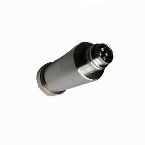
The VRT-2T is an integrated vibration sensor designed for continuous online monitoring of fans, pumps, and bearing housings on large and medium rotating machinery. It outputs a 4-20mA signal that connects directly to DCS for continuous tracking of both vibration and temperature. When the DCS reading diverges from what a portable instrument shows, the fault is somewhere in a chain that includes the sensor itself, the cable and signal path, and the DCS input channel. Narrowing it down quickly is what this article covers.
Why the Two Readings Might Not Match — Starting With the Basics
Before going into fault diagnosis, it’s worth acknowledging that some difference between a permanently mounted vibration sensor and a portable instrument is expected. The VRT-2T mounts at a fixed point on the bearing housing. A handheld meter might be placed nearby but not at exactly the same location, at the same angle, or with the same coupling force. Vibration amplitude can vary significantly even a few centimeters apart on a bearing housing, especially if the housing geometry is complex.
A difference of 10 to 20 percent between the two readings — particularly if the directional axis of measurement differs — can be entirely normal and doesn’t indicate a fault in either instrument. What raises a flag is a large sustained discrepancy, a DCS reading that doesn’t respond at all to changes in machine condition, or a reading that’s stuck at one value regardless of what the machine is doing.
With that baseline set, the diagnosis process works through three possible locations for a real fault: the sensor and its mounting, the signal transmission path, and the DCS input channel.
Step One — Check the Sensor Mounting
The most common reason an installed vibration sensor reads lower than a portable instrument is poor mechanical coupling between the sensor and the bearing housing surface. The VRT-2T needs firm, consistent contact with the measurement surface to accurately transfer vibration energy into the sensor element. If the mounting is loose, corroded, or there’s a thick layer of paint or surface rust between the sensor base and the housing, the vibration transfer is impaired.
Check the mounting physically. The sensor should be solidly attached with no rocking or movement when you apply hand pressure. If the mounting uses a stud or threaded boss, confirm it’s torqued correctly and that the contact face is clean metal-to-metal. Any flexibility in the mount acts as a mechanical filter — it attenuates the higher frequency components of vibration before they reach the sensor, which pulls the reading lower than actual.
Also check whether the sensor is mounted where the monitoring standard specifies. Feedwater pump bearing housing vibration is typically measured in the radial direction at the bearing centerline elevation. A sensor mounted on a bracket offset from that location, or in the axial direction when radial measurement was intended, measures something real but not necessarily what the portable instrument is measuring on the bearing housing itself.
Step Two — Check the Signal Path
If the sensor mounting looks correct and the physical installation is solid, the next place to look is the cable run between the sensor and the DCS input card. The VRT-2T outputs a 4-20mA current signal, which is inherently more resistant to cable-related errors than voltage signals — a small amount of cable resistance doesn’t shift the current reading the way it shifts a voltage reading. But cable problems can still cause issues.
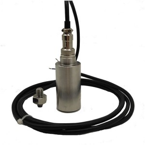
A partially broken conductor creates intermittent high resistance in the loop. This can cause the 4-20mA signal to fluctuate erratically or clip at certain points, producing a DCS reading that varies unpredictably rather than tracking actual vibration. A short between conductors, or between a conductor and the cable shield, pulls the loop current in a direction that shifts the DCS reading either high or low depending on the short’s location.
The field check here is straightforward. With the sensor powered and the machine running, measure the loop current directly at the sensor terminals using a clamp ammeter or by inserting a milliammeter in series with the loop at a convenient junction point. Note the current value. Then check what value the DCS is displaying and convert it back to the expected current using the sensor’s range: 4mA = 0 mm/s (or whatever the sensor zero is), 20mA = full scale. If the current you measured in the loop matches what the DCS is calculating from the received signal, the cable path and DCS channel are both fine, and the sensor or its mounting is where to focus.
If the current you measured differs from what the DCS displays, the DCS channel or its input configuration has an error — the signal is getting there correctly but the DCS isn’t interpreting it correctly.
Step Three — Check the DCS Channel
DCS analog input channels can develop faults — zero offset, gain error, or complete failure — without flagging themselves obviously as hardware faults. A channel with a calibration offset reads every sensor connected to it slightly high or low. A channel with a gain error compresses or expands the reading across the range.
The simplest field check uses a loop calibrator. Disconnect the sensor from the DCS channel and connect the calibrator in its place. Inject a known current — 4mA for zero, 12mA for mid-scale, 20mA for full scale — and observe what the DCS displays at each injection point. The DCS should show the corresponding value from the sensor’s configured range. If it doesn’t, the channel calibration has drifted or the input configuration is wrong.
This test also catches wiring errors in the DCS termination — a channel configured for the wrong range, or with an incorrect scaling factor entered — that would make a correctly functioning sensor appear to read incorrectly.
Quick Diagnosis Reference
| Symptom | Most Likely Cause | Field Check |
|---|---|---|
| DCS reads consistently lower than portable meter | Poor sensor mounting or measurement point mismatch | Check mounting torque, surface condition, sensor location vs. spec |
| DCS reading doesn’t change when machine condition changes | Sensor failure, broken cable conductor, or stuck DCS channel | Measure loop current at sensor terminals; compare to DCS display |
| DCS reading fluctuates erratically | Intermittent cable fault or loose terminal connection | Check cable continuity; inspect all terminal connections in the loop |
| DCS reads correctly at rest but wrong under vibration | Loose sensor mount acting as mechanical filter | Apply hand pressure to sensor during operation; check for movement |
| Loop current correct but DCS value wrong | DCS channel calibration error or wrong scaling configuration | Inject known current with loop calibrator; check DCS display at each point |
A Note on Measurement Frequency Range
One source of genuine discrepancy that’s easy to overlook is the frequency range each instrument is measuring. The VRT-2T is designed for bearing housing vibration on large rotating machinery — its measurement bandwidth covers the frequency range relevant for that application, typically 10 Hz to 1000 Hz or similar. A portable vibration instrument might have a different frequency range setting, or might default to a broader range that includes high-frequency components the VRT-2T wasn’t designed to capture.
If the portable instrument is set to a wider frequency range than the installed sensor’s bandwidth, it will read higher — because it’s summing vibration energy from frequency ranges the permanent sensor isn’t measuring. This isn’t a fault in either instrument. It’s just that they’re measuring different things. Confirming that both measurements are made over the same frequency range and in the same parameter (velocity in mm/s, displacement in µm, or acceleration in g) is part of a valid comparison.
When to Replace the Sensor vs. Investigate Further
After working through the three checks — mounting, signal path, DCS channel — the fault is usually identifiable. A sensor that measures correctly in the loop current test but has a loose mount can be remounted and rechecked. A DCS channel with confirmed calibration error can be recalibrated. A cable with an intermittent fault can be repaired or replaced.
The situation that points toward sensor replacement is a sensor that shows correct supply voltage, correct loop current at rest, but doesn’t respond to vibration changes that are clearly present. If the loop current holds steady at one value while the portable meter shows significant vibration variation, the sensor element itself has likely failed — the internal transducer is no longer converting vibration into a current signal change.
Bearing housing vibration sensors on feedwater pumps and other critical rotating equipment are usually accessible enough that replacement during a planned maintenance window is straightforward. If the VRT-2T on a particular bearing has been flagged as suspect, keeping a spare on site avoids the situation where a sensor confirmed as failed has to stay in place while procurement is sorted out.
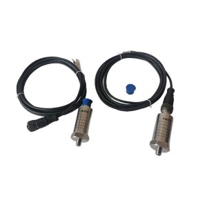
If you’re sourcing VRT-2T sensors for an existing installation or evaluating them for a new monitoring application, confirming the measurement range and output configuration against your DCS input card specifications before ordering avoids scaling mismatches that add unnecessary troubleshooting steps during commissioning.
Summary
A discrepancy between a VRT-2T DCS reading and a portable vibration meter reading isn’t automatically a sensor problem. It could be the sensor mount, the cable, or the DCS channel — and working through those in order with simple field measurements usually identifies the fault without much guesswork.
Measure loop current at the sensor terminals. If it matches what the DCS should be displaying, the cable and channel are fine and the sensor or its mounting is where to look. If the loop current is correct but the DCS displays something different, inject a known calibration current and check the channel. Those two steps resolve most discrepancies without needing to pull the sensor or dig into the DCS configuration beyond what’s accessible from the field.
Post time: Jul-20-2026
-

Polyester sleeve fiberglass Rope
-
RTV Silicon steel sheets adhesive J0705
-

Servo Manifold Spray HP Bypass Oil Filter C6004...
-

mechanical trip isolation valve F3DG5S2-062A-22...
-

CWY-DO Steam Turbine Eddy Current Sensor
-

Steam turbine servo valve PSSV-890-DF0056A
-

Generator stator cooling water filter SGLQB-1000
-

Single Channel Speed Monitor D521.02
-

Oil filter coarse filter DR913EA10V/-W
-

Generator motor electric tool carbon brush
-

LVDT displacement Sensor 2000TD
-

Platinum thermal resistance temperature sensor ...