

The ME8.530.024 is the board inside an electric valve actuator that handles the analog signal connection to the DCS or PLC. It takes in the 4-20mA command signal from the control system and sends back the valve position feedback. When this board fails, both of those functions can go at once — and what the valve does next isn’t always obvious or consistent.
That’s the part that actually matters from an operations standpoint. A valve that moves to the wrong position during a board fault is a worse problem than the fault itself. Knowing what your actuators are set up to do in this situation — and whether you can change that — is worth understanding before it happens on a live unit.
What the Board Is Doing During Normal Operation
The ME8.530.024 sits inside the actuator housing and manages two signal paths. Coming in: a 4-20mA command signal from the DCS, where 4mA usually means fully closed and 20mA means fully open. The actuator control module reads that current and drives the motor to the corresponding valve position.
Going out: a 4-20mA feedback signal back to the DCS showing where the valve actually is. The position sensor inside the actuator — usually a potentiometer — measures the stem position, and the board converts that into an analog output the control system can read.
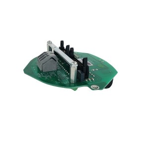
Two separate circuits, but they share the same physical board. A fault can knock out one or both, and you don’t always know which until you start looking at the symptoms on each side.
When the Command Input Is Lost
If the board fault kills the command input — or the 4-20mA signal drops out for any other reason — the actuator has to do something. What it does depends on how it was set up during commissioning. There are really three possibilities:
- Hold last position — stays where it was when the signal dropped, doesn’t move until a valid signal comes back or someone operates it manually
- Drive to a preset position — moves to a configured position, either fully open, fully closed, or something in between
- De-energize — motor cuts out and the valve ends up wherever line pressure and gravity leave it
Which of these happens is set in the actuator’s main control module, not in the I/O board itself. But here’s the thing — a board fault doesn’t always look like a clean signal loss to the main control electronics. If the fault causes the command input circuit to output a fixed voltage rather than going silent, the main controller might read that as a valid position command rather than a fault condition. In that case, the actuator drives to whatever position corresponds to that voltage, and the configured fail-safe behavior never triggers at all.
That’s a scenario worth thinking about. Testing what your actuator actually does when the signal is interrupted — rather than assuming the commissioning settings are correct — gives you a real answer.
When the Position Feedback Output Fails
A board fault that takes out the feedback output instead of the command input shows up differently. The valve might actually be responding to commands just fine — but the DCS is getting a bad feedback signal, or no signal at all.
Most DCS control loops will alarm on a lost or out-of-range feedback signal and drop out of automatic mode. Operators see what looks like a position feedback fault or a control loop error. The valve isn’t necessarily in trouble, but the control system doesn’t know that. If the loop tries to correct what it thinks is a position error based on wrong feedback, it can move the valve away from where it should be.
This is one reason board faults on the ME8.530.024 don’t always show up as the valve going to the wrong place. Sometimes the symptom is a DCS alarm about feedback, a loop that keeps dropping to manual, or an apparent position discrepancy that doesn’t match what you see at the valve itself.
Can the Fail-Safe Position Be Configured?
Yes, on most electric actuators that use an actuator control module like this one. The common options are:
- Fully closed on signal loss — standard choice for isolation valves and anything where the safe default is no flow
- Fully open on signal loss — used where cutting off flow is actually the worse outcome, like cooling water supplies or turbine seal systems
- Hold last position — when wherever the valve was at the time of the fault is acceptable and moving to an extreme would cause bigger problems
- Move to a defined intermediate position — less common, but some actuator platforms support it for applications where neither extreme works
Configuration is typically done through DIP switches or software parameters in the main control module, usually at commissioning. If that was done correctly, the actuator should behave predictably on signal loss. If it was never set — or was set to the wrong option for the application — the valve might not go where the process safety analysis assumed it would.
It’s worth checking what your actuators are actually configured to do, especially on valves that haven’t been touched since they were first commissioned.
Working Out Where the Fault Is
When the DCS is showing something wrong — bad feedback, valve not responding, unexpected position — the I/O board is one possible cause but not the only one. Working through the signal chain before pulling the board saves time.
| What You’re Seeing | Likely Cause | Quick Check |
|---|---|---|
| No valve movement, command signal present | Board input fault, cable break, or power supply issue | Measure 4-20mA at actuator terminals — is the signal getting there? |
| Valve moves but DCS shows wrong position | Feedback output circuit on board has failed | Measure feedback current at DCS end; compare to actual valve position |
| Position feedback stuck at one value | Board output frozen, position sensor failed, or cable fault | Move valve manually — if feedback doesn’t change, it’s board or sensor |
| Valve drives to extreme position unexpectedly | Signal loss with fail-safe configured to open or close | Check command signal continuity; verify what the fail-safe is set to |
| Erratic valve movement | Noisy command signal, board power issue, or loose terminal | Check signal quality at board terminals; check supply voltage |
Swapping the Board Out
Replacing the ME8.530.024 is usually not complicated. The board mounts inside the actuator enclosure with plug-in connectors or terminal blocks — no soldering, no special equipment. De-energize the actuator, swap the board, restore power.
The part that trips people up is what happens after. If configuration parameters were stored on the old board rather than in the main control module, those settings need to be re-entered on the replacement. Fail-safe position, signal range, any scaling adjustments — all of it needs to be verified, not assumed.
After any board replacement, running through the commissioning checklist and specifically testing the fail-safe behavior — actually interrupting the command signal in a controlled way and watching what the valve does — confirms the replacement is set up correctly. It takes a few minutes and it’s a much easier conversation than explaining an unexpected valve movement during live operations.
If you’re sourcing replacement ME8.530.024 boards, confirming compatibility with your specific actuator model and firmware revision before ordering is worth doing. A board that arrives and can’t be configured the same way as the original adds an unnecessary complication to what should be a straightforward swap.
Bottom Line
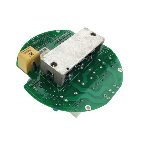
The ME8.530.024 handles two things — taking in the position command and sending back position feedback. A fault can affect either one or both, and the symptoms at the DCS don’t always make it clear which circuit has the problem.
What the valve actually does during a board fault depends on the configured fail-safe behavior and whether the main control electronics interpret the fault as a genuine signal loss. Knowing what your actuators are configured to do — and testing that configuration — is the preparation that keeps a board fault from turning into a process problem.
Post time: Jul-23-2026
-

4.5A25 Hydrogen system brass safety release valve
-

WTYY series Bimetal Thermometer Temperature Gauge
-

Sealing Oil Differential Pressure Valve KC50P-97
-

Reverse Rotation Speed Sensor CS-3F
-

Gear Oil Pump GPA2-16-E-20-R6.3
-

Regeneration device ion resin filter element DZ...
-

Pressure Switch ST307-V2-350-B
-

Polyester sleeve fiberglass Rope
-

Solvent-free RTV Epoxy adhesive 53841YR
-

EH oil system globe valve SHV20
-

EH oil regeneration filter ZX-80
-

Steam Turbine EH Oil System Servo Valve 072-559A