

When an LVDT position sensor on a steam turbine valve starts giving bad readings or the connecting rod fails, the investigation usually starts with the sensor itself. Was it a manufacturing defect? Did the coil fail? Is the signal conditioner the problem? Often the answer is none of those — it’s how the sensor was installed. Connecting rod failures on LVDT displacement sensors are frequently the result of installation errors that put mechanical stress on a component that wasn’t designed to carry it.
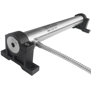
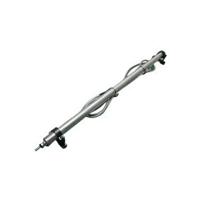
The HTD-300-3 is an LVDT position sensor used on steam turbine valve applications — measuring the stroke position of control valves, stop valves, and actuator assemblies to feed position feedback into the DEH control system. Getting the installation right isn’t complicated, but it does require attention to a few specific details that are easy to overlook when there’s pressure to get a turbine back in service.
What Actually Causes Connecting Rod Failures
The LVDT connecting rod — the mechanical link between the sensor’s moving core and the valve stem or actuator — is designed to transmit linear displacement along one axis. That’s it. It’s not built to handle side loads, angular forces, or bending stress. When the installation introduces any of these, the connecting rod is working against forces it wasn’t sized for, and fatigue failure follows.
The three most common installation-related causes come up repeatedly in field experience: misalignment between the sensor axis and the direction of valve travel, insufficient support for the sensor body that allows it to move under vibration, and fastener loosening that gradually lets the sensor shift from its set position over time.
All three are preventable. None of them require special tools or unusual skills — they just require doing the installation carefully rather than quickly.
Alignment: The Most Important and Most Ignored Step
The HTD-300-3 LVDT sensor measures displacement along the axis of the sensor core. The connecting rod transfers that displacement from the valve stem to the core. For the measurement to be accurate and for the connecting rod to survive in service, the sensor axis needs to be parallel to — and ideally coaxial with — the direction of valve travel.
When the sensor is angled relative to the stroke direction, even slightly, the connecting rod has to flex laterally on every stroke cycle. At 3000 rpm turbine operating conditions with the valve cycling regularly, that’s a lot of flex cycles accumulating on a component that was designed for pure linear travel. Fatigue cracks initiate at the flex point, usually at the rod-to-core connection or at the clevis pin joint, and the rod eventually fractures.
Checking alignment before final tightening is the step that prevents this. With the sensor body loosely mounted and the connecting rod attached to the valve stem, manually move the valve through its full stroke range. The rod should travel smoothly with no binding, no lateral deflection visible, and no angular change in the rod’s orientation relative to the sensor body. If any of those are present, the sensor mounting position needs to be adjusted before the fasteners are tightened.
Some installations use a universal joint or a flexible coupling between the connecting rod and the valve stem specifically to accommodate small angular errors. This is a reasonable approach for installations where perfect coaxial alignment is difficult to achieve — but it’s not a substitute for getting the alignment as close as practical. A flex coupling handles small angular deviations; it doesn’t compensate for a sensor mounted at a significant angle to the stroke direction.
Supporting the Sensor Body Against Vibration
Steam turbine valve areas are not quiet environments. The actuator itself generates vibration during operation, the piping and valve body transmit vibration from the flowing steam, and on turbines running at full load the background vibration level in the bearing pedestal and casing areas is substantial. An LVDT position sensor mounted on a bracket that allows any resonant vibration in the sensor body is going to have problems.
The sensor body needs to be supported along its length, not just clamped at one end. A single clamp at the sensor flange or mounting thread leaves the sensor body free to vibrate cantilevered about that single support point. The vibration amplitude at the sensor tip — where the connecting rod attaches — can be significantly larger than at the mounting point, even if the mounting point itself is rigid.
For sensors of the HTD-300-3′s length, a second support point along the sensor body reduces vibration amplitude at the tip substantially. The support doesn’t need to be a full clamp — a bracket with a close-fitting bore that the sensor body passes through, allowing the sensor to slide axially for adjustment during installation but providing radial support once tightened, is a common and effective arrangement.
When designing or fabricating the mounting bracket, consider the resonant frequency. A thin, long bracket arm can itself resonate at frequencies excited by the turbine operating speed. If possible, use a bracket geometry that’s stiff enough to have a resonant frequency well above the frequencies present in the environment.
Fastener Loosening Over Time
The turbine environment doesn’t just vibrate at startup and full load — it vibrates continuously, at varying frequencies, for years. Fasteners that are tight at installation gradually work loose under sustained vibration unless they’re positively secured against rotation.
Standard bolt and nut combinations are not enough on their own for LVDT sensor mounting in this environment. The specific approach depends on the mounting hardware design, but the options include:
- Lock nuts — a second nut tightened against the first, or a prevailing-torque nut that requires significant force to rotate, keeps the primary fastener from backing off under vibration
- Spring washers or tooth lock washers — these bite into the mating surface and provide resistance to rotation, effective for bolt heads and nuts on brackets
- Thread-locking compound — suitable for fasteners that don’t need frequent removal; provides reliable anti-rotation without adding hardware, but limits how often the joint can be disassembled cleanly
- Safety wire — used on critical fasteners in high-vibration environments where other methods aren’t sufficient; adds a physical connection between adjacent fasteners that prevents either from rotating independently
The choice depends on whether the sensor needs to be removable for maintenance and how frequently. For sensors that come out at every major overhaul, thread-locking compound on a primary fastener that’s expected to be broken loose annually is fine. For sensors that stay in place for years between outages, safety wire or prevailing-torque hardware gives better long-term security.
The Connecting Rod Joint — Where Things Go Wrong Most Often
The joint between the connecting rod and the valve stem gets less attention than the sensor body mounting, but it’s where a lot of failures actually occur. If this joint has play in it — even a small amount — that play becomes a hammering load every time the valve changes direction. On a valve that’s cycling regularly under DEH control, that hammering wears the joint quickly.
Clevis pin joints should be fitted with pins that are snug in both the clevis bore and the mating eye without being so tight that they can’t be removed for maintenance. A pin that’s loose enough to rattle is too loose. The pin should be retained with a proper cotter pin or a clip that prevents it from walking out under vibration — not just left in position by friction.
The connection between the connecting rod and the LVDT core should also be checked. If the rod threads onto the core, the thread engagement should be sufficient and the joint should be locked — either with a lock nut against the core end or with thread-locking compound if the design allows it. A connecting rod that can rotate on the core changes the effective rod length and shifts the zero reference of the position sensor over time.
Installation Checklist at a Glance
| Installation Step | What to Check | Common Failure If Skipped |
|---|---|---|
| Sensor axis alignment | Sensor axis parallel to valve stroke direction; no binding through full travel | Lateral bending stress on connecting rod; fatigue fracture |
| Sensor body support | Two support points for longer sensors; bracket stiffness adequate | Resonant vibration at sensor tip; connecting rod fatigue |
| Fastener locking | Lock nuts, locking washers, or thread-lock on all mounting hardware | Sensor shifts from set position; gap and alignment errors develop |
| Clevis pin joint | Snug pin fit; cotter pin or clip retention installed | Impact loading at joint; accelerated wear and play development |
| Rod-to-core connection | Thread engagement adequate; joint locked against rotation | Rod length shifts over time; position zero reference drifts |
| Full-stroke check | Smooth travel through complete stroke range before final tightening | Binding or angular stress on rod not detected until failure |
After Installation — What to Verify Before Commissioning
Once the HTD-300-3 is mounted and all fasteners are secured, a few checks before the turbine goes back in service confirm the installation is correct and give a reference baseline for future maintenance.
Drive the valve through its full stroke — from fully closed to fully open and back — while watching the position sensor output signal. The output should change smoothly and consistently with valve travel, with no steps, dropouts, or nonlinear sections. Any irregularity in the output during a slow manual stroke points toward a mechanical binding issue in the connecting rod or a coaxiality problem in the sensor mounting that wasn’t visible during static alignment checks.
Record the output voltage at the mechanical closed and open stops of the valve. These values become the reference points for calibration verification at future outages. A sensor that’s shifted from its installed position will show different end-point voltages — that change tells you the position has moved before you need to physically inspect the mounting.
If you’re sourcing HTD-300-3 sensors for an upcoming overhaul or need installation guidance specific to your valve configuration, having the actuator travel range and stroke length confirmed before ordering ensures the sensor’s measurement range is correctly matched to the application.
The Short Version
Most connecting rod failures on LVDT position sensors come back to three things: misalignment putting bending stress on the rod, inadequate support allowing vibration to fatigue the connection, and fasteners loosening over time and letting the sensor shift. None of these are difficult to prevent — they just require going through the installation carefully rather than treating it as a quick job.
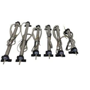
The HTD-300-3 displacement sensor is a reliable component for steam turbine valve position measurement when it’s installed correctly. Getting the alignment right before tightening, supporting the sensor body properly, using locking hardware throughout, and verifying smooth travel through the full stroke before commissioning are the steps that separate an installation that lasts years from one that needs attention at the next outage.
Post time: Jul-15-2026
-

Gas turbine actuator filter DP309EA10V/-W
-

Generator stator cooling water filter SWFY3 DN100
-

Surface cover epoxy air-dry varnish 1504
-

CQJ type accumulator Gas charging tool
-

Pressure Switch ST307-V2-350-B
-

Stator coil surface HR anti-corona varnish 1244
-

Steam Turbine EH Oil System Servo Valve 072-559A
-

Flow Control Servo Valve 072-1202-10
-

EH main oil pump inlet filter element OF3-20-3R...
-

Generator Oil-resistant Rubber Round Strip
-

WZPM2-001 PT100 Platinum thermal resistance The...
-

LVDT Position Sensor HTD-100-3