

Turbine speed measurement has an awkward range problem built into it. A probe that’s tuned to catch every detail of a machine spinning at 3000 rpm often struggles to say anything meaningful about the same shaft turning at 4 rpm on barring gear. The QBJ-CS-2-2 speed sensor handles this with an automatic switching function — one mode above 150 rpm, another below it. Simple concept. But the questions engineers actually ask about it are more specific than that, and they deserve straight answers.
The Question Everyone Actually Wants Answered First
Can this probe reliably see a shaft turning at barring gear speed — somewhere around 3 to 5 rpm — and produce a signal strong enough for the monitoring system to actually trust? Short answer: yes, that’s specifically what the low-speed mode is designed for. But “yes” deserves some explanation, because the physics involved aren’t as forgiving at low speed as they are at running speed.
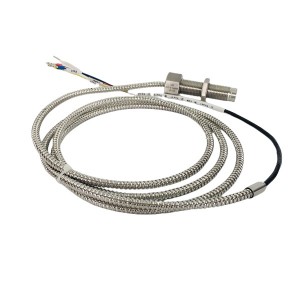
A magnetic pickup or similar speed sensor generates its signal based on the rate of change as gear teeth pass by — faster passing teeth generally means a stronger, cleaner signal. At 4 rpm, teeth are passing the sensor face very slowly compared to normal operating speed, and that naturally produces a weaker signal amplitude than you’d get at thousands of RPM. This is exactly why a dedicated low-speed mode exists rather than expecting one universal setting to handle both ends of the range well.
How the Low-Speed Mode Compensates
Below the 150 rpm threshold, the QBJ-CS-2-2 switches its internal processing to handle the weaker, slower signal characteristic of barring gear and very low turning speeds. This typically involves adjusted signal amplification and different filtering parameters tuned for low-frequency pulse detection, rather than the parameters used for the higher-frequency signal at running speed.
The practical result, when everything’s set up correctly, is that even a signal amplitude that would be considered too weak for high-speed mode gets properly recognized and processed in low-speed mode. This is really the whole point of having two modes instead of one compromise setting — each mode is optimized for the signal characteristics actually present in that speed range.
Why 150 RPM Specifically?
This threshold isn’t an arbitrary round number chosen for convenience. It sits in a zone that’s meaningfully above typical barring gear and turning gear speeds (usually single digits to low tens of rpm) while still comfortably below the speed range where a turbine transitions from slow warming rotation into active acceleration toward synchronous speed.
Setting the threshold too low would risk the switch happening too late during startup acceleration, potentially catching the probe still in low-speed mode while the shaft has already sped up enough that low-speed signal processing isn’t appropriate anymore. Setting it too high risks the opposite — switching into high-speed mode prematurely, before the shaft has actually reached a speed where high-speed signal processing works reliably.
150 rpm sits in a practical middle ground for most steam turbine startup profiles, giving enough margin above barring gear speed and below the point where acceleration typically becomes rapid, so the transition happens in a speed zone where signal characteristics from both processing modes still overlap reasonably well.
The Transition Zone — Where Things Get Genuinely Tricky
Here’s the part worth taking seriously. During the actual startup sequence, as the turbine accelerates from barring gear speed up through and past 150 rpm on its way to higher speeds, there’s a transition window where the measurement system has to switch modes in real time, based on live signal behavior rather than a scheduled event.
Is there a risk of signal instability during this transition? Yes, and it’s worth being honest about that rather than pretending the switch is always perfectly clean. A few things can happen right around the threshold crossing.
What Can Go Wrong Near the Threshold
- If turbine acceleration is uneven or fluctuating slightly right around 150 rpm — which can happen during certain startup conditions — the measured speed might cross back and forth over the threshold briefly, causing the mode switching logic to toggle rather than settling cleanly into one mode.
- A brief, minor signal dropout or noise spike right at the transition point could, in some circumstances, cause a momentary misread of actual speed, especially if the switching logic doesn’t have adequate hysteresis built in around the threshold.
- Mechanical factors — slight variations in gear tooth spacing, minor probe gap inconsistency, electrical interference from nearby equipment during startup — can all compound right at this transition point in ways that wouldn’t be noticeable in the middle of either speed range.
Well-designed systems address this with hysteresis — meaning the switch-up threshold and switch-down threshold aren’t exactly the same number, but offset slightly, so a speed hovering right at 150 rpm doesn’t cause rapid mode toggling back and forth. If your installation is showing signs of unstable readings specifically during this transition, checking whether adequate hysteresis is configured is one of the first things worth investigating.
Practical Steps If You Suspect Transition Instability
- Review speed trend data specifically through the 100 to 200 rpm range during recent startups, looking for any erratic jumps, brief dropouts, or unusual noise that doesn’t match the smooth acceleration you’d expect mechanically.
- Confirm hysteresis settings on the switching logic match manufacturer recommendations rather than a default value that might not suit your specific turbine’s typical acceleration rate through this range.
- Check probe gap and mounting condition, since a probe sitting slightly further from the gear than specified will produce weaker signals across the board, making the transition zone more vulnerable to the instability described above.
- If instability is confirmed and traced to the switching logic itself rather than a mechanical or wiring issue, consult the manufacturer about adjusting the hysteresis band or threshold configuration for your specific acceleration profile.
| Speed Range | Mode | Key Consideration |
|---|---|---|
| 3-5 rpm (barring gear) | Low-speed mode | Weak signal amplitude, requires low-speed amplification and filtering |
| Approaching 150 rpm | Transition zone | Risk of mode toggling without adequate hysteresis |
| Above 150 rpm | High-speed mode | Standard high-frequency signal processing, stronger signal characteristics |
Why This Level of Detail Actually Matters
Speed measurement during barring gear operation and during the early stages of startup acceleration isn’t just a data point for the control room to watch. It often feeds into interlocks and permissive logic — confirming the shaft is actually turning before certain systems are allowed to proceed, or confirming acceleration is progressing normally rather than stalling somewhere it shouldn’t.
A speed probe that produces a marginal or unreliable signal at barring gear speed, or that behaves erratically during the transition through 150 rpm, can create confusing indications right at moments when clear, trustworthy speed data actually matters most — startup being one of the more procedurally sensitive phases of turbine operation.
If your plant is evaluating a QBJ-CS-2-2 installation or reviewing an existing one that’s shown questionable behavior during startup, it’s worth requesting the manufacturer’s documentation on hysteresis configuration and low-speed signal amplitude specifications, so field settings can be checked against what the design actually calls for rather than assumed from general practice.
A Few Installation Details Worth Getting Right From the Start
- Confirm probe gap is set to the manufacturer’s specified value and verified after any maintenance work near the gear, since gap drift over time can quietly degrade signal strength at exactly the low-speed range where margin is already tighter.
- Check that the gear used with this probe meets the tooth profile and pitch requirements specified for reliable low-speed detection — a worn or poorly profiled gear compounds the inherent weak-signal challenge at barring gear speeds.
- Document actual switching behavior observed during commissioning, including speed values where mode changes were noted, as a baseline reference for comparison if transition behavior seems to change over time.
Final Thoughts
The QBJ-CS-2-2 speed probe is built specifically to handle the awkward reality that turbine speed measurement spans a huge range, from a few rpm on barring gear up to full operating speed, and no single processing approach handles both extremes well. The low-speed mode genuinely can produce a usable signal at barring gear speeds, assuming the probe gap and gear condition are within spec. The 150 rpm threshold sits in a sensible zone based on typical startup profiles, though the transition through that point deserves attention, since hysteresis and mechanical condition both play a role in how cleanly that switch actually happens.
For a measurement this tied to startup permissive logic, it’s worth confirming the details rather than just trusting the switch works perfectly by default. A few checks during commissioning, and a periodic look at startup trend data afterward, go a long way toward catching a transition problem before it becomes a recurring source of confusing readings.
Post time: Aug-26-2026
-

Duplex oil filter DQ150AW25H1.0S
-

Hydraulic oil filter element LX-HXR25X20
-

Oil purifier circulating filter element HC8314F...
-

Duplex Armored Thermocouple WRKK2-221
-

Accumulator Rubber Bladder NXQ-A-25/31.5
-

Low resistance anti-corona tape
-

GJCF-15 APH Gap Control system Signal Transmitter
-

EH oil main pump skeleton oil seal TCM589332
-

AST solenoid valve GS021600V
-

Servo valve SM4-40(40)151-80/40-10-H919H
-

Dual color water level meter B49H-10/2-W
-

High Temperature steam turbine cylinder sealing...