

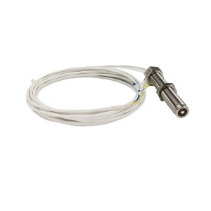
Frequency tells you speed. Amplitude tells you something else — how much signal the sensor is actually managing to generate. On a magnetoelectric speed sensor, watching amplitude slowly drop while frequency stays exactly where it should be is a specific kind of warning, different from a sensor going noisy or a reading jumping around. The SZMB-9 rotation speed sensor is built for exactly this measurement on high-speed steam turbines, and when its output starts weakening gradually with installation clearance already ruled out, there are a few real explanations worth working through.
How This Sensor Makes a Signal Without Any Power
A magnetoelectric speed sensor is passive. No external supply, no battery, nothing plugged in to make it work. It generates its own signal through electromagnetic induction — a magnet inside the sensor creates a magnetic field, and as a ferromagnetic target (a gear tooth, an impeller blade, a hole in a perforated disc) passes near the sensor tip, it disturbs that field. That disturbance induces a voltage in the sensor’s coil. One tooth passing, one pulse. Faster rotation, more pulses per second, which is where frequency comes from. The size of each pulse — the amplitude — depends on how strong the magnetic disturbance actually is at the moment it happens.
This is why the sensor needs no lubrication and no external power. It also means signal strength is entirely dependent on the health of a fairly small number of physical things: the magnet’s field strength, the coil’s condition, and the gap between the sensor tip and the target.
Where It Gets Used and Why Amplitude Actually Matters
On high-speed steam turbines, this sensor measures rotational speed by reading a gear, impeller, or similar ferromagnetic feature as it rotates past the sensor tip. Speed measurement itself relies mostly on frequency — that part of the signal is fairly robust even as amplitude weakens, at least initially. But amplitude isn’t just a cosmetic number. A signal that’s dropped too far can start getting missed entirely by downstream signal conditioning equipment, especially at low speeds where the signal is naturally weaker to begin with. A weakening trend, caught early, gives time to plan a fix before the signal actually becomes unreliable rather than just smaller.
Frequency Normal, Amplitude Dropping: What That Combination Rules Out
If frequency stays accurate and consistent, the sensor is still correctly detecting each tooth passing by — timing is intact. What’s degrading is how strongly each pass gets registered. That distinction matters, because it points away from anything that would disrupt timing itself (a target with damaged or missing teeth, for instance, tends to show up as frequency irregularities, not just weaker amplitude) and toward something affecting signal strength specifically.
Three Candidates Behind a Fading Signal
Long-term exposure to high temperature can gradually demagnetize the internal magnet. Magnets lose strength slowly under sustained heat, and a turbine environment, especially close-coupled installations, can run warmer than a sensor’s magnet would ideally prefer over years of continuous service. A weaker magnetic field means a weaker induced voltage for the exact same mechanical motion — same target, same gap, same speed, less signal.
An inter-turn short circuit developing in the coil changes the coil’s effective output characteristics, including its output impedance. Insulation between windings can degrade over time from heat and vibration, and even a partial short — not a complete failure — can reduce the effective voltage the coil delivers for a given magnetic field change. This produces a similar symptom to magnet weakening, but from a completely different internal failure mechanism.
Wear on the speed-sensing gear teeth increases the effective air gap in the magnetic circuit, even without the sensor’s own mounting position changing at all. If the gear teeth themselves wear down, becoming shorter or less sharply defined, the target moving past the sensor disturbs the magnetic field less than it used to, purely because there’s less ferromagnetic material closing the gap at the moment of closest approach. This is worth separating clearly from installation clearance — the sensor-to-target mounting distance hasn’t changed, but the target’s own geometry has, which produces a functionally similar effect on signal strength.
Sorting These Three Apart
None of these three can be told apart by amplitude alone, since all three produce the same basic symptom — weaker signal, same frequency. A few additional checks help.
Checking coil resistance and comparing it against the sensor’s original specification is a fairly direct way to investigate the inter-turn short theory. A short typically changes the measured coil resistance from its as-manufactured value, sometimes noticeably, sometimes only slightly depending on how many turns are affected. If resistance measures close to the original spec, a coil short becomes less likely, and attention shifts toward the magnet or the gear teeth.
Inspecting the gear teeth directly, visually and with basic measurement if the target is accessible, settles the wear question with reasonable confidence. Visible flattening, rounding, or reduced tooth height compared to a new or known-good gear confirms wear as a contributing factor, independent of anything happening inside the sensor itself.
Comparing the sensor against a second, newer or known-good unit, if one is available and can be installed temporarily under the same conditions, helps isolate whether the fading signal really is sensor-side at all, rather than target-side. If a fresh sensor produces a stronger signal at the same physical location and target condition, the original sensor’s magnet or coil is implicated. If the fresh sensor also shows a comparatively weak signal, gear wear becomes the more likely shared cause.
Using RMS Voltage as a Trend, Not Just a Reading
Measuring the RMS value of the sensor’s AC output voltage on site is a practical, non-invasive way to track this over time, and it works considerably better as a trend than as a single snapshot reading. One measurement tells you where things stand today. A series of measurements, taken at consistent operating speed and logged over months or years, tells you how fast the signal is actually declining — which is the number that actually matters for planning ahead.
Comparing a current RMS reading against historical baseline data, ideally recorded at the same rotational speed each time since amplitude scales with speed, gives a genuinely useful indication of how much service life margin remains before the signal risks becoming unreliable. A slow, steady decline over years suggests gradual magnet demagnetization, the most common of the three causes simply because it’s a function of time and temperature that affects every unit eventually. A faster decline, or one with a noticeable step change at some point, is more consistent with either a coil fault developing or a period of accelerated gear wear.
This comparison has limits worth being honest about. RMS voltage alone can’t distinguish a magnet problem from a coil problem from a gear problem with full certainty — it only tells you that something in the signal path has weakened and roughly how quickly. The additional checks described earlier are still needed to pin down which of the three is actually responsible, but the RMS trend is what tells you it’s time to go looking in the first place, often well before the drop is severe enough to affect actual speed measurement reliability.
Practical Steps for Ongoing Monitoring
Recording RMS output voltage at a fixed, repeatable operating speed as part of routine condition monitoring builds the historical baseline this whole approach depends on. Without that baseline, a single reading taken after a complaint has already surfaced tells you far less than the same reading compared against years of prior data would. Periodic visual inspection of the speed-sensing gear during scheduled outages, where access allows, catches tooth wear before it becomes a major contributor to signal loss. Coil resistance checks during the same outages add another data point without requiring the sensor to be removed from service for long.
Specification Points for Replacement or New Installations
Confirm the sensor’s rated operating temperature range against the actual ambient conditions at the mounting location, since sustained temperatures near or above that rating accelerate magnet aging. Confirm the expected air gap and target material specification match the actual gear or impeller in service, since air gap tolerance varies by sensor design and affects baseline signal strength from day one. Confirm whether the manufacturer provides guidance on expected long-term amplitude degradation rates, which — where available — gives a useful reference point for judging whether an observed decline is within normal aging behavior or unusually fast.
Where This Leaves the Diagnosis
A speed sensor losing amplitude while frequency stays clean isn’t really a mystery on its own — it’s a short list of three physical explanations, each leaving slightly different fingerprints once you look past the RMS number itself. Coil resistance checks the short-circuit theory. A look at the gear teeth checks the wear theory. What’s left over, after ruling those two in or out, is most likely a magnet that’s simply run warm for too many years. Tracking RMS voltage against a real historical baseline is what turns a one-time gauge reading into an actual early-warning system for all three.
| level transmitter KCS-15/16-900/3/10 | surface temperature probe k type TE-205 | speed sensor CS-075-3900/13 |
| Eddy Current Sensor PR6424/011-110 | intelligence Hand Operator NPDF-Q110D4 | Expanda Cable Coil for soot blower IK-530 |
| Servomotor position transducer DET700B | Eddy Current Sensor PR6422/002-141 | best proximity sensor TM301-A02-B00-C00-D00-E00-F00-G01 |
| Sensor PT-100 RTD Thermocouple Head WZP2-2212 | Fan propeller TFE630C-115B6 KM11010087 | Eddy Current Sensor PR6426/000-030 |
| Eddy Current Sensor PR6424/101-011 | Eddy Current Sensor PR6424/004-001 | precision pressure transducer 403216-29QL14 |
| RTD SENSOR PT100 WZPM2-08-78-M18-S | Temperature sensor PT 100 WZPM2-001 Pt100 L=40 | Water level gauge B49H-10/2-W |
| Motor protection controller MMPR-220 | LVDT actuator travel sensor 191.36.09(1).01 | Controller RPCF-16 |
| Eddy Current Sensor PR6424/101-121 | Current Sensor Limit Switch KD10-1Z | CLAMP METER 773 |
| linear encoder for hydraulic cylinder TD-1 940MM | LVDT Sensor 4000TDGNK-30-01 | best thermocouple WRN2-630 LX1=225*76 |
| Eddy Current Sensor PR6423/001-100 | DIFFERENTIAL PRESSURE SWITCH 101NN-KK3-N1-C1A | MEH Speed Sensor D-075-02-01 |
Post time: Sep-15-2026
-

Sealing ring DG600-240-07-03
-

Ion exchange resin filter element HQ25.300.21Z ...
-

Generator stator cooling water filter SGLQB-1000
-

DET Series Displacement Sensors
-

LVDT Position Sensor 3000TD
-

EH oil online filter machine fine filter JLX-30...
-

Jacking oil pump discharge filter DQ8302GAFH3.5C
-

LVDT Position Sensor HL-3-100-15
-

EH oil main pump suction filter HQ25.200.11Z
-

Reverse Rotation Speed Sensor CS-3F
-

22FDA-F5T-W220R-20LBO cone valve type plug sole...
-

Circulating oil pump oil-return working filter ...