

Turbine casing expansion has to be watched closely during startup and load changes. Too much differential expansion, and clearances inside the turbine start closing up in places they shouldn’t. The TD-2-26 is an LVDT displacement sensor built for exactly this measurement, feeding both a local dial and a remote DCS display. Most of the time the two agree. When they start drifting apart, and the sensor’s own linearity has already been checked and cleared, the mismatch has to be sitting somewhere in the mechanical or electrical path between the sensor and the two displays.
The Sensor Itself
An LVDT works by moving a core through a coil assembly, producing an electrical signal proportional to displacement. No sliding electrical contacts, no wear-prone electronics doing the actual sensing — which is a large part of why this sensor type holds up well over years of continuous operation. Range is configurable to suit different turbine casings, and rated accuracy sits at ±1% of full scale.
Two output paths come off this measurement. A local mechanical dial, driven by the physical displacement through some kind of linkage. A remote signal, converted electrically and sent to the DCS. The sensor itself only knows about the displacement of its probe rod. Everything past that point is where a local-versus-remote disagreement actually gets introduced.
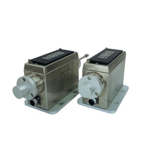
Two Displays, One Measurement, Two Separate Paths to Get There
The local dial isn’t reading the LVDT’s electrical output. It’s typically driven by a direct mechanical connection to the probe rod, or connected through the same rod that also drives the sensor’s electrical measurement, depending on the specific mounting arrangement. That mechanical linkage has moving parts — pivots, linkages, gearing in some designs — and mechanical parts wear.
The remote path goes through signal conditioning electronics, which converts the LVDT output into whatever signal format the DCS expects. That conversion has a zero point and a span, both of which can shift slightly over time, the same way any analog instrumentation can drift with age and thermal cycling.
Between the sensor and both displays, there can also be a connecting rod or coupling — a physical link transferring the actual casing movement to the sensor’s probe. If that connection develops play, movement at the casing doesn’t fully translate to movement at the sensor, and neither display gets accurate information, though not necessarily by the same amount.
Ruling the Sensor Out First
The scenario here already assumes sensor linearity has been checked and isn’t the issue. That’s an important starting point, because it means the LVDT itself is producing an electrical output that accurately reflects the actual position of its own probe rod. Whatever’s wrong is happening either before the probe rod gets that information, or after the sensor produces its signal.
Three Places the Discrepancy Could Live
Wear in the local dial’s mechanical linkage is one candidate. Pivots loosen, linkages develop play, and over years of continuous casing movement, the connection between actual displacement and where the pointer actually sits can degrade. The dial can end up decoupled from true position — moving less than it should, sticking slightly, or lagging behind actual movement.
Zero-point drift in the remote transmitter is another. If the signal conditioning electronics have shifted their zero reference, the remote reading offsets from true value by a roughly constant amount, even though the sensor’s actual output relative to displacement stays linear and correct.
Looseness or lost motion in the connecting rod between the sensor and the casing is a third, and this one’s a bit different from the other two because it can affect both displays simultaneously, rather than just one. If the rod has play in it, some casing movement gets absorbed by that play instead of being transmitted to the sensor probe. Both local and remote readings would then be behind actual casing movement, though whether they’d show it identically or differently depends on exactly where the play sits relative to each pickoff point.
The Manual Push Test
Pushing the probe rod by hand, carefully, while watching both displays at the same time, is a genuinely useful field check, and it works because it isolates the sensor and its immediate readouts from actual turbine operation entirely.
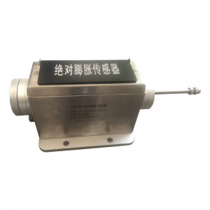
If both the local dial and the remote display respond immediately and track the manual push consistently, with the same relative movement, the sensor and both readout paths are behaving correctly when directly driven. That would mean the discrepancy seen during actual operation is happening upstream of the probe rod — most likely in the connecting rod linking the sensor to the casing, since that’s the piece not exercised by a manual push at the probe itself.
If the local dial lags or sticks during the manual push, not moving smoothly or fully matching the actual rod movement, that points toward wear in the local dial’s own linkage. This isolates the fault to the mechanical display path specifically, independent of the remote signal or the casing connection.
If the remote display shows a fixed offset from where it should read, but tracks changes proportionally and smoothly as the rod moves, that’s more consistent with a zero-point shift in the transmitter rather than a mechanical wear problem — the electronics are still responding correctly to displacement, just with an incorrect baseline.
Reading the Test Results Together
If the “thrust test” indicates that both indicators function correctly in isolation, one can effectively rule out the sensor, local linkage, and remote transmitter as the causes of the deviation observed during actual operation. It can thus be inferred that the issue likely lies with the connecting rod between the sensor and the housing; once the test points to this component, it is necessary to directly inspect the connection for any clearance or looseness.
If the thrust test reveals a malfunction in one indicator while the other operates normally, the problem can be specifically isolated to that particular signal path, eliminating the need to inspect all other components first.
It is worth noting that the manual thrust test is conducted under static, controlled conditions and may not fully replicate the various scenarios—such as thermal cycling, vibration, or full-stroke housing movement—encountered during actual operation. Even if the thrust test yields normal results, they serve only as a strong indicator rather than an absolute guarantee that intermittent faults will not occur elsewhere under dynamic operating conditions.
Maintenance Around This Kind of Sensor
Periodic manual verification, even without an active complaint, gives a baseline to compare against later if a discrepancy does eventually show up. Checking local dial linkage for play during scheduled outages, when the unit is accessible, catches developing mechanical wear before it becomes noticeable during actual operation. Verifying remote transmitter zero calibration against a known reference position periodically helps catch drift early, before it accumulates into something significant enough to notice on the DCS trend. Inspecting the connecting rod for looseness at the same intervals closes out the third possible source before it becomes a real discrepancy.
What to Confirm When Specifying This Sensor
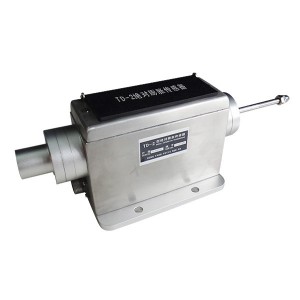
Confirm the measurement range configured for the specific turbine casing and expansion characteristics involved, since this is a user-set parameter rather than a fixed value across all installations. Confirm the local dial mechanism type and its expected mechanical service life, since this varies by design and affects how often linkage wear should realistically be expected. Confirm the remote signal type and its compatibility with the actual DCS input configuration, along with the transmitter’s stated long-term zero stability specification.
The Short Version
Local dial and remote display disagree, sensor linearity already cleared — the fault sits in one of three places: the mechanical linkage behind the dial, the zero point inside the remote transmitter, or the connecting rod carrying real casing movement to the sensor. A careful manual push at the probe rod, watched on both displays at once, sorts out most of that without needing to touch anything on the turbine itself.
| Air dryer – water cooled refrigerated SDLW-25 | intelligence Hand Operator NPDF-Q110 | SET TAKE UP ADJUSTER ASSEMBLY GT2150007 |
| BENTLY Preamplifier 330180-90-00 | Galvanized cables with red sheath XY2CZ105 | Feedwater Pump Speed Probe CS-3F-M10-L55-1 |
| LVDT TD-1 0-110 | TEMPERATURE DIGITAL WP-C403-01-08-HL | intelligence Hand Operator NPDF-Q210D3 |
| End surface thermal resistance WZPM201 | Stainless quake-proof manometer YTA-100-BF | Speed sensor CS-1-D-100-02-01 |
| protect unit 7SJ6241-5EB90-3FE0 | Brush Holder HDK-3 | Frequency digital display KLY-F96-G 100V |
| TEMPERATUR DIGITAL DISPLAY XMTJ-2032 | LVDT Sensor TD-7500 | Speed Converter 330103-00-08-10-02-00 |
| intelligence Hand Operator NPDF-Q20F0 | Intelligent current distributor MIC04.6 | AUXILIARY RELAY JZ-7-3-204B (XJZY-204B) |
| Laser sensor JGS-600 | Eddy Current Sensor PR6424/101-021 | DC contactor CZ0-400/20TH |
| RTD WZP2-235 | best oil tank level monitor 397001-N33519 | Mitsubishi Gas Turbine Module FXDIM01 |
| high temperature differential pressure transducer RC861CZ090H | Pressure switch B461B | Heater JHG03S2-380V/6KW |
Post time: Sep-14-2026
-

DN80 Sealing oil vacuum tank floating valve
-

Boiler Tube sliding block
-

188 generator rotor surface red insulating varnish
-

Hydraulic Accumulator NXQ-A-6.3/31.5-L-Y
-

LVDT Position Sensor HTD-100-3
-

FY-40 floating valve of Generator seal oil floa...
-

Magnetic reed switch (sensor) CS1-F
-

KR-939SB3 Integrated Three-Parameter Combinatio...
-

Hydraulic oil filter element LX-HXR25X20
-

Regeneration device anion filter PA810-002D
-

LVDT Position Sensor TD-1 0-100
-

Stator Cooling Water Pump YCZ50-250C