

A boiler feed pump that’s been in service for a few years doesn’t announce balance drum wear with an obvious alarm. What it does instead is shift load — gradually, quietly — from the balance drum to the thrust bearing. By the time the thrust bearing temperature is climbing fast enough to get attention, the clearance between the balance drum and its liner has usually been out of specification for a while. The damage is already accumulating.
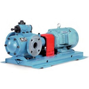
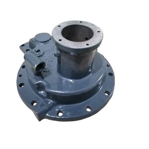
The HPT-300-340-6S is the balance drum assembly used in the HPT300-340 horizontal multistage barrel-casing cartridge pump. Its function is to generate a counteracting axial force using the pressure differential across the drum, offsetting the majority of the axial thrust produced by the impellers. What’s left after that compensation goes to the thrust bearing. That arrangement works well when the drum clearance is within specification. When the clearance grows through wear, the drum’s ability to compensate drops, and the thrust bearing picks up the slack.
Understanding how that process shows up in the operating data — before the bearing is in serious trouble — is what this article covers.
Why Balance Drum Clearance Grows and What It Costs
The balance drum sits close to a stationary liner with a precise radial clearance — typically fractions of a millimeter at installation. This clearance controls how much high-pressure water leaks across the drum from the high-pressure side to the low-pressure balance line. That leak flow, combined with the pressure difference, is what generates the balancing force.
Over time, a combination of particle erosion from the feedwater, minor shaft movement, and occasional contact during transient conditions gradually wears both surfaces. The clearance opens up. When it does, more water leaks through, the pressure differential across the drum decreases, and the balancing force the drum produces falls below what it was providing at the original clearance.
The impeller-generated axial thrust hasn’t changed. The drum just isn’t countering as much of it anymore. The residual thrust that the thrust bearing was originally designed to handle — a relatively small load — now includes whatever the drum is no longer compensating for. Depending on how far the clearance has drifted, the thrust bearing could be carrying significantly more than its design load.
Thrust bearings in boiler feedwater pump service are sized with a specific load capacity. Running them above that capacity isn’t immediately catastrophic, but it accelerates the Babbitt surface wear rate and raises operating temperature. Run them hard enough for long enough and the bearing fails — sometimes progressively through wear, sometimes suddenly through overtemperature.
What the Operating Data Shows as Clearance Grows
This is where early detection becomes practical. The pump’s monitoring systems — directly connected to the DCS in most power plant installations — are generating data that reflects balance drum condition continuously. The information is there. The question is whether anyone is looking at the right parameters in the right way.
Thrust Bearing Temperature
This is the most direct indicator. As the balance drum clearance grows and the thrust bearing absorbs more residual axial load, the bearing metal temperature rises. The rise isn’t usually dramatic at first — it might be a degree or two per month over many months of gradual wear. That’s slow enough that any single reading looks normal compared to the day before.
What catches it is trending over time, not point-in-time comparison. A thrust bearing temperature that was stable at 65°C twelve months ago and is now consistently sitting at 72°C — with the same load, the same coolant temperature, the same operating conditions — is telling you something has changed in the axial load the bearing is carrying. The balance drum is the first place to investigate.
The active side of the thrust bearing typically shows the temperature rise first, because the unbalanced axial thrust pushes the rotor in one direction and loads one side of the thrust bearing more than the other. If active and inactive bearing temperatures start diverging over time, that asymmetry is a useful early signal.
Axial Displacement
Most boiler feed pumps in power plant service have axial displacement probes on the shaft, typically eddy current type, monitored continuously by the TSI system or equivalent. The displacement reading shows where the rotor is sitting axially within the bearing clearance at any given moment.
A healthy pump with a properly functioning balance drum has relatively stable axial displacement — the drum holds the rotor in approximately the same axial position under steady load conditions. As drum clearance grows and the balancing force becomes less effective, the rotor tends to shift slightly toward the active thrust bearing face. The displacement reading moves in that direction and may show more variability than before, because the rotor is less firmly held in position.
A steady drift in the mean axial displacement value over weeks or months — rather than a sudden shift — is characteristic of gradual drum wear. Sudden shifts usually indicate something more acute: a balance line blockage, a large change in operating point, or a shaft seal failure rather than drum wear.
Balance Line Flow and Pressure
Where instrumentation allows, monitoring the balance return line can provide supplementary information. As drum clearance grows, the leak flow through the drum increases. If flow measurement is available on the balance return line — not always the case, but present in some installations — an upward trend in balance return flow at constant pump operating conditions indicates the drum clearance is growing.
Balance line return pressure can also shift as clearance changes, though this is more complex to interpret because it’s affected by multiple variables simultaneously.
Early Warning Parameters at a Glance
| Parameter | What to Watch For | What It Suggests |
|---|---|---|
| Active thrust bearing temperature | Gradual upward trend over months at constant load | Increasing axial load on bearing — drum compensation declining |
| Active vs. inactive bearing temperature difference | Growing gap between the two sides | Asymmetric thrust loading — one drum face carrying more than designed |
| Axial displacement mean value | Slow drift toward active bearing face over weeks/months | Rotor shifting as drum balancing force weakens |
| Axial displacement variability | Readings becoming less stable at steady load | Drum holding rotor less firmly in position |
| Balance return line flow (if measured) | Gradual increase at constant operating point | Drum clearance growing — more leakage through the gap |
How to Build a Useful Trend From the Data
The challenge with gradual wear indicators is that any individual reading looks unremarkable. Trending works when you have consistent reference conditions. Thrust bearing temperature, for example, is affected by ambient temperature, cooling water temperature, pump load, and feedwater temperature — comparing a winter reading to a summer reading without accounting for those variables produces noise rather than signal.
The practical approach is to pull data at comparable operating conditions — same load band, similar feedwater temperature, same unit configuration — and plot those normalized readings over time. A month-by-month record of thrust bearing temperature during baseload operation, stripped of the seasonal and load-related variation, shows the underlying trend clearly.
Most DCS historians can produce this data with the right query. Setting up a simple monthly report on thrust bearing temperature and axial displacement trending costs almost nothing in terms of engineering time and gives operations and maintenance staff an early view of what the balance drum is doing between outages.
If the trend shows a consistent upward drift in thrust bearing temperature and a corresponding shift in axial displacement over a period of months, scheduling a boiler feed pump cartridge pull during the next available planned outage — rather than waiting for an alarm condition — allows the drum clearance to be measured and the HPT-300-340-6S balance drum assembly to be assessed or replaced before bearing damage forces an emergency shutdown.
When to Act on the Trend
There’s no single universal threshold that applies to every installation, because the baseline temperature and displacement values vary between pump designs, bearing types, and operating conditions. What matters is the rate of change relative to the established baseline for that specific unit.
A few indicators that suggest the situation warrants near-term action rather than continued monitoring:
- Thrust bearing temperature has risen more than 8 to 10°C above the established baseline at equivalent load conditions
- Active bearing temperature is consistently 5°C or more above the inactive side under steady operating conditions
- Axial displacement has drifted noticeably from the historical mean and is approaching the alarm setpoint rather than sitting comfortably below it
- The rate of temperature rise is accelerating — the slope of the trend is getting steeper rather than remaining constant
Any of these individually warrants a closer look. More than one appearing together at the same time suggests the balance drum clearance has moved beyond the point where monitoring and waiting is the right call.
For procurement planning around the HPT-300-340-6S balance drum assembly or related boiler feed pump internal components, confirming parts availability and lead times well before a planned outage avoids the situation where the maintenance decision is made but the parts aren’t available to act on it.
The Short Version
Balance drum wear in the HPT-300-340 boiler feed pump doesn’t announce itself loudly. It shows up as a slow rise in thrust bearing temperature, a gradual shift in axial displacement, and eventually — if it’s missed long enough — a bearing that’s been running above its design load for months. The data to catch it early is already being collected. Trending thrust bearing temperature and axial displacement against a normalized baseline, and reviewing that trend consistently rather than only when an alarm fires, is what separates catching drum wear at a planned outage from dealing with it as an emergency.
Post time: Jul-27-2026
-

Epoxy-ester air-drying red insulating varnish 9130
-

EH oil online filter machine fine filter JLX-30...
-

Fire-resistant oil filter DP401EA01V/-F
-

LVDT position sensor HL-6-50-15
-

Generator Stator Cooling Water Filter MSL-125
-

APH Gap Control System Gap Sensor Probe GJCT-15-E
-

Sealing Oil Vacuum Oil Tank Float Valve BYF-80
-

Hydraulic filter element LH0160D020BN3HC
-

HTD series LVDT displacement actuator position ...
-

Generator Epoxy adhesive DFCJ1306
-

Filter element MZFP-32-118 mesh
-

Steam turbine actuator oil filter DL004001