

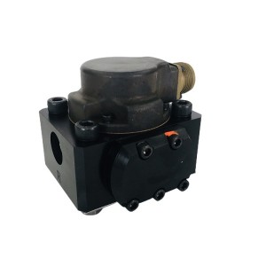
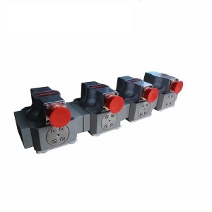
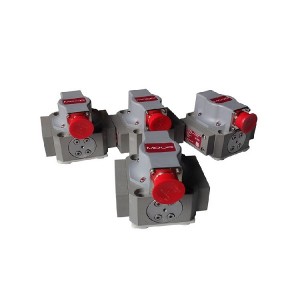
The steam turbine, the massive heart of the electric power world, relies on the synergistic work of a series of precision components for every steady beat. Among these critical control links, the servo valve plays a vital role. Today, we focus on a specific model: the Turbine Control Servo Valve 761K4112B. It acts like a sensitive electro-hydraulic converter, precisely executing instructions from the main control system to regulate the steam flow into the turbine, maintaining the unit’s speed and power output.
Control Valve Servo Valve: The Core of Precision Control
761K4112B, the number, represents a high-performance electro-hydraulic servo valve. Its basic function is to efficiently and linearly convert a weak electrical signal into powerful hydraulic energy, driving the fast and accurate movement of the turbine control valve (or governor valve). Its internal structure is extremely precise, primarily consisting of a torque motor, a nozzle-flapper system, and a spool-and-sleeve assembly.
Based on the unit’s load demand, the control system sends an electrical signal to the torque motor. The motor acts, moving the flapper toward the nozzle, changing the pressure difference between the two oil chambers, which in turn drives the main spool’s displacement. The displacement of the main spool directly controls the direction and flow rate of the high-pressure oil to the control valve hydraulic actuator. This process must be completed within milliseconds to ensure the dynamic response and steady-state accuracy of the turbine servo valve control. This requirement for high precision makes it extremely sensitive to oil cleanliness, ambient temperature, and its own mechanical condition.
Internal Wear and Stiction: The Direction of Failure Mode
When the 761K4112B servo valve operates for an extended period, especially with poor oil cleanliness or the presence of minute particulates, its internal precision mating surfaces—most commonly between the spool and the sleeve—may experience wear. Wear increases the mating clearance, leading to increased internal leakage, which in turn slows down the servo valve’s response speed, reduces control accuracy, or causes hysteresis near the null position, creating a control “dead zone.”
More severe and sudden than wear is stiction (or sticking). Stiction is typically caused by impurity particles in the oil, deposits of oxides on the spool surface, or micro-deformation due to localized stress concentration, causing the spool to encounter abnormal resistance during movement.
A crucial question arises: if this turbine control valve servo valve experiences internal wear or stiction, will its failure mode lead to the fail-safe side?
The “fail-safe side” refers to the system automatically or tending to enter a state that minimizes harm to equipment and personnel and is easiest to control when a fault occurs. For a turbine control valve, the fail-safe side usually means load reduction or even unit trip/shutdown (i.e., the control valve quickly closes, reducing steam admission).
However, for internal stiction faults in the servo valve, the failure mode does not always lead to the fail-safe side.
- Stiction in the Open or Intermediate Position: If the spool sticks in an open or intermediate position, and the control system is issuing a closing command (e.g., during load rejection), the servo valve will be unable to execute the closing action. This can cause the turbine overspeed protection system to intervene passively, and if the protection system fails to act promptly, it is highly likely to cause severe overspeed of the unit, thus threatening the integrity of the turbine itself. This “stiction-induced loss of control” is a catastrophic, non-fail-safe fault.
- Leakage Due to Wear: Internal leakage caused by wear primarily reduces the control stiffness. While not immediately catastrophic, it may lead to insufficient valve movement or oscillation during dynamic response (such as grid disturbances), indirectly affecting system stability.
Therefore, for critical components like the 761K4112B servo valve actuator, one cannot blindly assume that its failure mode is intrinsically fail-safe. Real-time monitoring and early warning become extremely important.
Characteristic Parameters for Early Fault Warning
Since failure is potential and non-fail-safe, are there characteristic parameters that can be used for servo valve early fault warning? The answer is yes. Through online monitoring and data analysis, subtle signs of the servo valve’s deteriorating condition can be captured.
- Dynamic Response Time (Dynamic Characteristics): Periodically or online test the servo valve’s response speed to step signals or sinusoidal signals. When internal wear or leakage intensifies, the time required for the spool to reach the target position will significantly increase, which is the most direct parameter for judging the decline in servo valve control performance.
- Relationship Between Input Current and Output Pressure/Displacement (Steady-State Characteristics): Record the control valve position or output pressure when the same control current is input to the servo valve. When wear and leakage occur, the valve displacement corresponding to the same current may become smaller or the linearity may worsen; when stiction occurs, the curve may show discontinuous “jumps” or a noticeable “hysteresis loop” in certain areas.
- Null Current (Null Bias): Monitor the servo valve input current required to keep the control valve position stable at the null position (or a fixed mid-position). If the null current drifts continuously and slowly over time, it is usually due to changes in the nozzle-flapper system spring characteristics or the accumulation of slight contamination, serving as an early signal of internal imbalance.
- Vibration and Noise: Abnormal mechanical wear or cavitation may cause changes in the characteristic vibration or noise of the servo valve body or oil pipes.
Long-term trend analysis of these servo valve fault characteristic parameters can provide valuable early warning information for power plant operation and maintenance personnel, enabling a shift from reactive maintenance to predictive maintenance.
Get in Touch
If your power plant is facing performance degradation or failure issues with the Turbine Control Valve Servo Valve 761K4112B, professional diagnosis and servo valve repair/replacement services are key to ensuring the unit’s safe and efficient operation.
Contact our technical team now to receive a status evaluation report and customized solution for your turbine high-pressure servo valve equipment, allowing your power assets to maintain stable output.
E-mail: sales@yoyik.com
Tel: +86-838-2226655
Whatsapp: +86-13618105229
Yoyik offers various types of power plants spare parts for steam turbines, generators, boilers as below:
Post time: Dec-05-2025
-
RTV Silicon steel sheets adhesive J0705
-

Hydraulic oil system filter element FAX 250*10
-

EH Oil Main Pump Discharge Oil Filter Element D...
-

SZCB-01 series Magneto-Resistive Speed Sensor
-

Jacking Oil Pump Suction Filter QF6803GA20H1.5C
-

Steam Turbine EH Oil System Servo Valve 072-559A
-

Filter element QF1D350CFLHC
-

Filter element QF1D350CJJHC
-

ZS-04 Rotational Speed Sensor
-

Pressure Switch ST307-V2-350-B
-

Hydraulic oil station precision fine filter UE3...
-

GDZ421 room temperature vulcanizing silicon rub...