

DCS says one voltage. The panel meter at the switchgear says another. Not wildly different — just off, consistently, by a small but noticeable margin. Someone’s already ruled out the PT secondary circuit. So the mismatch lives somewhere between the transmitter and the DCS input card, and that stretch has three suspects worth naming: the transmitter’s internal reference drifting with age, a range DIP switch set wrong, or the DCS analog input’s sampling resistor having shifted value.
What the Transmitter Actually Does
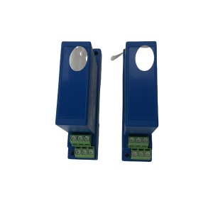
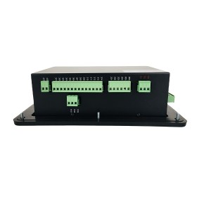
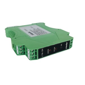
The S3-VD-3-15A40 voltage transmitter takes three-phase AC voltage as input and puts out a DC current or voltage signal, scaled linearly to the measured value. That output feeds into a DCS analog input channel, which converts it back into a displayed voltage using its own scaling. Two conversion stages, two chances for something to drift.
Mounting is on a standard 35mm DIN rail, per DIN 46277, which is mostly a mechanical detail — but it matters here because it means the unit is usually sitting in a cabinet alongside other DIN-rail equipment, exposed to whatever heat and vibration that cabinet sees over the years. The unit is built to tolerate pulses, surges, and vibration reasonably well. That doesn’t mean the internal reference never ages. It means it ages slower than a poorly protected design would.
Where This Fits in the Loop
In a power automation control system, this transmitter typically sits between the PT secondary and the DCS, converting the actual generator voltage into a signal the control system can read and display. Local panel meters often read from the same PT secondary independently, giving operators a way to cross-check the DCS value against something not routed through the transmitter at all. That’s exactly the comparison being described here — DCS reading versus panel meter reading, with a gap that shouldn’t be there.
Three Places a Constant Offset Can Come From
A steady, unchanging discrepancy — not something that jumps around, not something tied to load or time of day — points toward one of three fairly specific things.
The transmitter has an internal reference voltage that everything else in the unit scales against. That reference can shift slightly with age and thermal cycling. If it drifts, the output no longer matches the input the way it did when the unit was calibrated. This produces a shift that applies across the whole measurement range, not just at one point.
The range setting on the transmitter, set through DIP switches, tells the unit what input voltage range corresponds to its rated output. If someone set this incorrectly — during commissioning, or during a later parts swap where the switches weren’t checked against the actual PT ratio — the transmitter is scaling correctly according to its own settings, just against the wrong assumed input range. The output looks proportionally wrong across the board, in a way that can look a lot like reference drift from a distance.
The DCS analog input channel converts the transmitter’s current or voltage signal into a displayed value using a sampling resistor (for current-loop signals) or its own input scaling. If that resistor’s value has changed — from age, from heat, from a component tolerance issue — the DCS side is misreading a perfectly correct signal from the transmitter. In this case, the transmitter itself is doing nothing wrong at all.
A Quick Field Check That Actually Helps
Measuring current directly at the transmitter’s output terminal, with a calibrated meter, and comparing that reading against what the DCS is displaying for the same input voltage, separates these three possibilities faster than almost anything else available on site.
If the measured output current matches what the transmitter’s specification says it should produce for the actual input voltage, the transmitter is doing its job correctly. Whatever’s wrong is downstream — most likely the DCS-side sampling resistor or input scaling, not the transmitter.
If the measured output current does not match the expected value for the actual input voltage, the problem sits inside the transmitter. At that point, deciding between reference drift and a wrong DIP switch setting takes one more step.
Telling Reference Drift From a Wrong Switch Setting
Checking the DIP switch positions against the documented settings for the actual PT ratio and expected voltage range is the fastest way to rule this in or out. If the switches match documentation and match what the installation actually requires, the switch setting is not the cause, and reference drift becomes the more likely explanation by default.
If the switches don’t match — set for a different range than what the PT actually delivers — that alone can fully explain a proportional, constant offset without needing to invoke internal component aging at all. This is worth checking early, since it costs nothing but a look at the unit and its documentation, and it rules out a fairly common commissioning-era mistake.
Where switches check out correctly and output current still doesn’t match expected values for the input voltage, reference aging is the remaining explanation, and at that point recalibration or replacement of the transmitter becomes the reasonable path forward.
Why the DCS Side Deserves Equal Suspicion
It’s tempting to assume the field device is always the problem, since it’s out in the cabinet, exposed to the environment, and easier to picture failing. The DCS analog input card sits in a controlled environment, but its components age too, and a shifted sampling resistor produces exactly the kind of steady, proportional offset being described here — no different in appearance from a transmitter fault, until someone actually measures the current at the transmitter terminal directly.
This is really the value of that one field measurement. It draws a clean line between “the signal leaving the transmitter is correct” and “the signal leaving the transmitter is wrong,” which immediately tells you which side of the loop actually needs attention.
What a Consistent Offset Does Not Tell You
A constant, unchanging discrepancy rules out certain things by its own nature. It’s not a wiring fault that comes and goes with vibration. It’s not electrical noise, since noise tends to be intermittent or load-dependent rather than a fixed steady offset. A constant offset really does point toward one of these three calibration-and-scaling explanations, which is actually useful — it narrows the search considerably compared to an intermittent fault.
Keeping This From Happening Again
Periodic verification of transmitter output against a calibrated reference, done on a set schedule rather than only after a discrepancy is reported, catches reference drift while it’s still small rather than after it’s grown large enough for someone to notice on a panel meter. Documenting DIP switch settings clearly at commissioning, and checking them again after any card or module replacement in the loop, prevents the range-mismatch scenario from recurring during future maintenance work. Where DCS input cards are known to be aging or approaching their service life, periodic calibration checks on the input channel itself, not just the field transmitter, close the loop on the other side of the potential fault.
Specification Points Worth Confirming
For a three-phase voltage transmitter intended for this kind of application, confirm the accuracy class and expected long-term stability specification from the manufacturer, since these numbers directly bound how much drift to expect over a given service period. Confirm the DIP switch range options actually match the PT ratio and voltage range present in the installation, rather than assuming a default setting will be correct. Confirm output signal type — current or voltage — matches what the DCS analog input channel is actually configured to accept, since a mismatch here can look like a scaling problem even when both devices are individually working correctly.
One Measurement, One Answer
A mismatch between DCS and panel readings, once the PT circuit is cleared, comes down to a short list. Reference drift inside the transmitter. A DIP switch set for the wrong range. A shifted sampling resistor on the DCS side. One current measurement at the transmitter’s output terminal, checked against the DCS display for the same input, tells you immediately which half of the loop to keep looking at — and that alone usually cuts the investigation time in half.
| Solenoid valve R481716324 | solenoid valve 4WMM10G10-FMIV | ELECTRIC ACTUATOR M8340 |
| circulating pump F320V12A1C22R | Accumulator capsule NXQ-A-6.3/20.0-F | AST Control Block AST165.31.56.04.01 |
| Solenoid valve DG3VP-3-102A-VM-U-P-20 | solenoid valve GS061200N | valve AG R18514222X |
| Accumulator Bladder BNXQ-A-32/10-F-Y | O-ring HB4-56J1-20 | Drum connecting and regulating valve T962Y-25 |
| Small engine EH oil accumulator bladder AB-16/31.5-L-E | Pressure reducing valve A21F-16R | globe valve 65FWJ1.6P |
| switch valve FQ-5-250-1 | Accumulator NXQAB-100/10-F-Y | main sealing oil pump ACF090N4IRBP |
| vacuum pump sealing P-2332 | Accumulator bladder NXQB-10/10-L-A | Accumulator Bladder NXQ-A-50/31.5-L-E |
| vacuum pump lock nut Coml | Power plant shut-off valves WJ32F3.2P | ball valve BKH-20S-4425 |
| Vane pump PEED-4130045/015 | Accumulator bladder BNXQ-AB-40/2.5-F-Y | Mechanical shutdown electromagnet DFP-A1-DC110 |
| Bellows valves WJ41W-40P | PUMP 70LY-34×2-1B | Rubber sealing ring with circular cross-section HB4-56J1-52H |
Post time: Sep-14-2026
-

MM2XP 2-pole 24VDC Digital Power Intermediate R...
-

Generator stator cooling water filter SWFY3 DN100
-

EH oil main pump PVH098R01AD30A250000002001AB010A
-

Boiler Tube sliding block
-

Steam turbine servo valve PSSV-890-DF0056A
-

ZJ series steam turbine bolt heating rod
-

Actuator inlet oil filter AP6E602-01D10V/-W
-

Gear Oil Pump GPA2-16-E-20-R6.3
-

Cooling fan YB2-132M-4
-

Magnetic Rotation Speed Sensor ZS-01
-

Jacking Oil Pump Suction Filter QF6803GA20H1.5C
-

YSF series pressure relief valve for transformer