

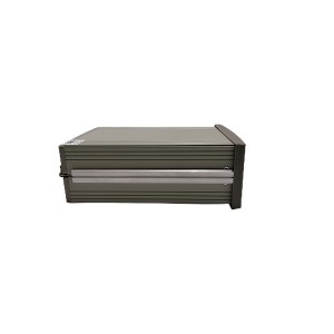
Big steam turbines go through massive temperature changes when you start them up or shut them down. When hot steam pours inside, the heavy steel shell expands quite a bit. This movement has to happen smoothly along the tracks on the floor. The HXW-R Thermal Expansion Monitor is the tool that watches this growth all the time. It makes sure that the huge casing moves without getting stuck or twisting out of shape.
As the turbine gets hot, the metal can grow by thirty or fifty millimeters depending on the machine size. If a sliding pin gets jammed or the grease dries up on the foundation blocks, the shell cannot move freely. It will distort and bend, which changes the tiny clearances inside between the spinning blades and the outer body. The monitor shows this absolute expansion value in real time so operators can catch problems before the internal parts start rubbing together.
The instrument uses two separate sensors to measure how much the shell moves relative to the concrete foundation. You install these sensors on both sides of the dead point on the turbine casing. By comparing the two numbers, the monitor can tell if the shell is growing evenly on the left and right sides. If one side stops sliding while the other side keeps moving, the monitor flags this uneven stress right away.
Picking the Right Range for the Sensors
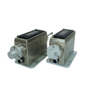
The HXW-R instrument is made to work with the TD-2 type thermal expansion sensor. This sensor is an LVDT, which stands for a linear variable differential transformer. It takes the sliding mechanical movement of the turbine and turns it into an electrical signal. The usual measuring ranges for these units are zero to thirty-five millimeters or zero to fifty millimeters. It is vital that you match the sensor stroke with the monitor settings when you set things up.
A very common mistake during maintenance upgrades is putting in a sensor but setting the wrong range inside the monitor menus. For example, if you have a fifty-millimeter sensor but the monitor is set for a thirty-five-millimeter scale, the data sent to the DCS will be wrong. You will get a non-linear distortion on your control screens. The numbers on the screen won’t match the real physical gap on the turbine floor, which means your automatic safety protection won’t work right.
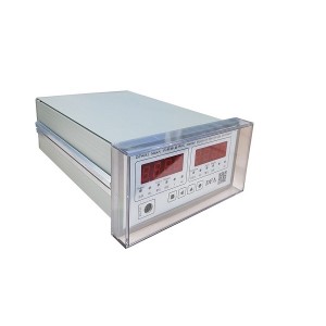
The front of the monitor has a very bright digital display that shows the live travel numbers clearly, even in a dark turbine hall. It also lets you set up two levels of safety alarms, which are usually labeled as “alarm” and “danger.” If you are having trouble matching your TD-2 sensor with a replacement instrument, our engineering desk can check your data sheets to help you find the exact model you need.
How Dual-Channel Tracking Saves Your Turbine Case
Watching the total growth is only half the job when you manage Casing Expansion Travel. A turbine shell might move thirty millimeters out from the center, but if the left side moves faster than the right side, the whole casing twists. This twisting puts a huge amount of stress on the sliding pin system under the bearing pedestals. The dual-channel design of the HXW-R lets it watch both sides of the machine at the exact same time.
The chip inside the monitor subtracts one side’s reading from the other side to find the difference. If the foundation rails are dirty or warped, one side of the turbine pedestal will hitch and jump. The difference value will start climbing fast. Operators can set a specific limit for this differential alarm to catch a stuck pedestal before the sliding keys get bent or permanently seized up.
The monitor sends these travel values back to the control room using standard 4-20mA current loops. This signal lets the main computer create history trends for the operators. By looking at these trends, maintenance teams can see exactly when the casing growth slows down or stalls during the heating cycle, making it easier to plan a rail cleaning during the next shutdown.
| What It Measures | Sensor Model | Standard Range | Main Safety Target |
|---|---|---|---|
| Absolute Casing Growth | TD-2 LVDT (One side) | 0–35 mm or 0–50 mm | Stops the shell from binding up completely |
| Side-to-Side Difference | Dual TD-2 Sensors | Calculated delta value | Stops sliding pins from bending and casing twisting |
| Analog Signal Output | 4–20 mA Loop | Matches the set scale | Sends live trend data to the main DCS |
Wiring Rules and Ground Loop Noise Problems
The TD-2 displacement sensor uses a medium-frequency differential transformer design inside. This design gives it good protection against high heat and magnetic fields around the turbine floor. However, the wires running between the hot sensor and the control cabinet can still pick up electrical noise. This is why you must always use shielded cables for these installation paths.
The wiring must follow the single-ended grounding rule strictly. The cable shield should only connect to the ground bar inside the instrument cabinet. The sensor end of the shield must be cut short and taped up so it cannot touch the turbine frame or the local junction box. This keeps the electrical path clean by only grounding the wire at one point.
If the installation crew connects the shield layer to the signal terminals by mistake, or if they ground it at both ends, you will have serious trouble. Grounding both ends creates a ground loop because the electrical potential of the turbine base is almost never the same as the control cabinet ground. This loop creates a lot of AC hum and random voltage spikes in the circuit. The numbers on your Turbine Case Expansion Monitor will start jumping around wildly, which triggers false alarms or hides a real case jam.
Testing and Calibrating the Setup
Checking the expansion monitoring system should be part of your yearly outage work. Because these sensors live in a rough environment with constant vibration and high heat, the mounting brackets can slip over time. Technicians need to check both the mechanical zero point and the full-scale output on a regular schedule to ensure accuracy.
To do a test, you move the sensor rod manually using a micrometer calibration jig while the turbine is cold and shut down. The technician checks that the display on the front of the instrument matches the physical displacement at twenty-five, fifty, and one hundred percent of the stroke. If the readings don’t match as the rod pulls out, it usually means the range settings inside the monitor are wrong, or the internal coil inside the TD-2 sensor is damaged.
- Look at the outer conduit to make sure it isn’t cracked or hardened from the heat.
- Check the insulation resistance of the shielded wire to see if any water got into the boxes.
- Make sure the alarm relays flip their switches correctly when the test values go past the limits.
- Clean off any old grease or grit from the sliding rod of the sensor so it doesn’t stick.
Our warehouse keeps a regular stock of original replacement instruments and matching position sensors for different turbine frames. If your readings are jumpy during startup or if you need a full kit for an upcoming maintenance outage, you can contact our sales department for quick pricing and delivery options.
Conclusion
The HXW-R Thermal Expansion Monitor is a key piece of gear for protecting big turbine casings when they heat up and cool down. By watching the total growth and the side-to-side difference with two TD-2 sensors, it keeps the sliding pins from getting bent by binding forces. You must select the right range and use proper single-ended grounding to keep the signal free from distortion and electrical noise.
Spending a little time checking the cable shields and sensor alignment during regular shutdowns stops expensive false trips and keeps your automation data clean. If you want to replace an old tracking unit or update your instrumentation layout, feel free to send us your current part numbers. Our team is ready to give you full technical sheets and help you find the right parts for your plant upgrade.
E-mail: sales@yoyik.com
Tel: +86-838-2226655
Whatsapp: +86-13618105229
Yoyik offers various types of power plants spare parts for steam turbines, generators, boilers as below:
Speed measuring instrument JNJVS3900/13-A01-B03-C036-D060
Transformers oil-surface thermometer BWY-804JJ(TH)
dp sensor RC0410CZ090Z
SoftLogic control software MPROG-PRO0535E
Limit Switch SP-3969
Signal regulator MSC307-B0C0
TIMER NJS1-2Z
Shaft vibration probe 111-402-000-013-A1-B1-C042-D000-E050-F1-G050-H05
Steam turbine bolt electric heater ZT-20-T6
Limit Switch DELLX918-11L
linear sensors TDZ-1E-021 0-175
analog cylinder position sensor TDZ-1B-32
THERMOCOUPLE,DUAL WRNK2-73
Eddy Current Sensor PR6422/102-020
thermal resistance WZPK2-335
3D Swelling Indicator SYZQ500×500-300
Eddy Current Sensor PR6424/011-121
SENSOR POSITION LVDT LP BY PASS ZDET-150A
bolts heater 1.2311(4)-φ18X600
Speed sensor DSE1210.00 SHZ
Magnetic liquid level gauge UHZ-R000100-1.0-1800
Post time: Jun-05-2026
-

Epoxy phenolic glass cloth laminated pipe
-

MFZ-4 steam turbine cylinder sealing grease
-

HSN series three-screw pump
-

Oil pump discharge flushing oil filter DP602EA0...
-

Epoxy Phenolic Anti-Corona Laminated Glass Clot...
-

SM4-20(15)57-80/40-10-S182 actuator electro-hyd...
-

Hydraulic oil system filter element FAX 250*10
-

Dual color water level gauge Tempered glass acc...
-

Hydraulic oil return filter element MF1802A03HVP01
-

Epoxy Phenolic Laminated Glass Fabric Slot Wedg...
-

4.5A25 Hydrogen system brass safety release valve
-

Cooling fan YB2-132M-4