

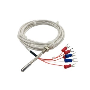
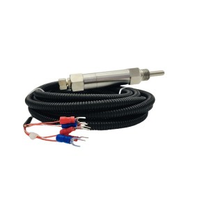
The WZPK2-336S is a dual-element armored Pt100 temperature sensor built for continuous bearing temperature monitoring on steam turbines, feed pumps, fans, and similar rotating machinery. Both Pt100 elements share the same stainless steel armored sheath with magnesium oxide fill, and both are intended to read the same temperature independently. When they start reading differently, the gap between them carries information that’s worth understanding before it’s dismissed or acted on incorrectly.
Construction and Operating Context
The WZPK2-336S uses imported thin-film Pt100 elements — Class A accuracy, which specifies a tolerance of ±(0.15 + 0.002|T|)°C across the operating range. At 100°C, that’s approximately ±0.35°C per element. Two Class A elements in the same sheath should, under identical conditions, read within less than a degree of each other if both are functioning correctly.
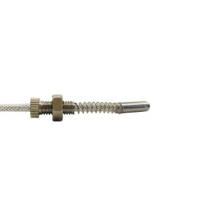
The armored construction — MgO-filled stainless steel sheath — gives this temperature sensor its mechanical flexibility and resistance to vibration, oil, and pressure. For turbine thrust bearing and journal bearing applications, where the sensor body is routed through drilled passages in the bearing housing, the ability to follow a curved path without damaging the sensing element is essential. The sheath diameter for this model (implied by the “336″ designation range) allows passage through standard bearing housing bores.
The dual-element configuration means each element connects to its own DCS input channel through separate wiring. The two channels operate independently. Neither powers the other. This independence is the foundation of the redundancy — but it also means each element and its associated signal chain can develop its own faults independently of the other.
How DCS Deviation Logic Works — and What It Protects Against
For critical protection measurement points — turbine thrust bearing temperature in particular — the DCS typically applies a dual-channel deviation alarm rather than simply selecting one channel as primary and ignoring the other. The logic compares the two readings continuously. If the difference exceeds a defined threshold, usually set somewhere between 3°C and 8°C depending on the application and the plant’s protection philosophy, the deviation alarm activates.
When the deviation is confirmed persistent (not a transient), the logic can be configured to automatically suppress the suspect channel — typically the one with the higher reading, on the assumption that a high-reading fault is more likely than a high-reading true bearing temperature. This prevents a single faulty channel from triggering an unnecessary trip on a healthy bearing. It also alerts maintenance that one element needs attention.
The protection this logic provides is real. A single-element sensor that drifts high will eventually trigger a bearing trip on a machine that is running normally. With dual elements and deviation logic, the system catches that drift before it reaches the trip threshold and flags the discrepancy rather than acting on it immediately. That’s the intended function.
The risk runs in the other direction too. If the deviation threshold is set wide — 8°C or 10°C — the logic won’t trigger until the gap is already significant. A sensor that has drifted 6°C is not producing a useful reading, but it hasn’t triggered the deviation alarm. The two channels appear to be in acceptable agreement while one of them has meaningfully degraded.
The Blind Spot: Thresholds That Are Too Wide
Setting the deviation threshold too conservatively is often done to avoid nuisance alarms from normal measurement scatter. The reasoning is understandable — a threshold that triggers too frequently trains operators to ignore the alarm. But the tradeoff is reduced sensitivity to early degradation.
A sustained 3–5°C gap between the two elements, sitting below the alarm threshold, is not benign information. Two Class A Pt100 elements in the same sheath, measuring the same temperature, should agree within about 0.5–1°C over most of their operating range. A persistent 4°C deviation means something has changed in one or both channels. It’s a signal worth investigating, not a margin to consume before the alarm triggers.
The practical implication is that deviation alarm thresholds should be chosen based on the actual accuracy specification of the installed sensors, not on a round number that seems safe. For Class A Pt100 elements at bearing temperatures of 60–100°C, a threshold of 3°C already allows for substantial degradation on one element before the alarm fires. A threshold of 5°C or more risks missing early drift entirely until it accelerates.
Distinguishing Cable Degradation from Element Drift
When a persistent 3–5°C deviation exists between the two channels of a WZPK2-336S installation, the first question is whether the fault is in the cable and connection circuit or in the sensing elements themselves. The answer changes what needs to be repaired.
Cable and Connection Faults
Increased contact resistance at a terminal block, oxidised crimp connections, or partial conductor damage in the extension cable all add resistance in series with the Pt100 element. For a three-wire or four-wire Pt100 connection, a series resistance error translates directly into a positive temperature offset — the DCS reads higher than actual temperature.
The diagnostic test for cable faults is straightforward. With the sensor accessible, measure the total cable loop resistance from the DCS input terminal back to the sensor connection head — ideally without disconnecting the sensor, using a milliohmmeter or a Kelvin bridge at the input card terminals. Compare against the known cable resistance specification for that run length and cable cross-section. An unexplained increase in loop resistance confirms a cable or connection fault, not a sensor element fault.
Cable faults also tend to affect one channel while leaving the other unchanged, since each element uses separate wiring. If one channel’s cable loop resistance has increased while the other is normal, that channel’s elevated reading is likely cable-driven, not a sign of element drift.
Element Performance Degradation
Pt100 element drift is a real phenomenon over long service periods, particularly in high-temperature applications. Thin-film elements — which the WZPK2-336S uses — can show resistance drift caused by strain changes in the platinum film, contamination of the film substrate from diffusion through the MgO fill at elevated temperatures, or mechanical stress from vibration cycling. The drift is almost always positive — the element reads higher than calibrated over time.
Element drift is distinguishable from cable faults by the character of the deviation. Cable faults tend to be step-like — the reading shifts when a connection is disturbed and stays at the new level. Element drift is gradual and progressive — the deviation between channels grows slowly over months or years rather than appearing suddenly.
A deviation that appeared within a week of the last maintenance visit in the area is more likely a cable or connection fault. A deviation that has grown steadily over the past year, trending slowly from 1°C to 4°C on the channel records, is more likely element drift. Both conclusions can be confirmed with an off-site calibration check on the removed element.
Replacement Timing: When to Change Both Elements Together
The dual-element design creates a maintenance timing question that single-element sensors don’t have: when one element is confirmed faulty and needs replacement, should the other element be replaced at the same time?
The argument for replacing both simultaneously is straightforward. Both elements have the same installation history — the same vibration exposure, the same thermal cycling, the same MgO fill environment. If one has degraded to the point of replacement, the other is likely at a similar stage of its service life even if it currently reads within specification. Replacing only the faulty element restores the redundancy configuration, but the remaining element may follow within a short interval — requiring a second outage access to the bearing housing.
On installations where bearing housing access is straightforward, replacing one element and monitoring the other closely may be acceptable. On turbine bearings where sensor access requires partial disassembly, the outage cost of a second replacement within a year almost always exceeds the cost of a new WZPK2-336S installed during the first visit.
A practical replacement policy for turbine bearing temperature sensors of this type:
- Replace both elements simultaneously whenever one element is confirmed faulty during a planned outage
- Establish a maximum service life based on operating hours — typically 40,000–60,000 hours for continuous high-temperature bearing service — after which both elements are replaced regardless of current reading
- If a deviation alarm triggers between planned outages and access is available, confirm the fault by cable resistance check first; if cable fault is ruled out, replace both elements at the next maintenance window rather than waiting for the second element to also fail
- Record the deviation trend in the DCS historical data as part of the sensor’s service record — this data supports both the replacement decision and the interval review
Deviation Pattern Quick Reference
| Deviation Pattern | Most Likely Cause | Recommended Action |
|---|---|---|
| Sudden step change in one channel; deviation stable at new level | Cable connection fault — terminal oxidation, loose crimp, cable damage | Measure cable loop resistance on the affected channel. Check and re-terminate connections at both ends before considering sensor replacement. |
| Gradual, progressive increase in channel deviation over months | Pt100 element drift — typical of long-service thin-film elements in high-temperature vibration environments | Schedule replacement of both elements at next planned outage. Calibrate removed elements off-site to confirm drift magnitude. |
| Intermittent deviation — appears and disappears without pattern | Intermittent contact fault — loose terminal screw, marginal crimp, cable flexing at a routing point | Inspect cable route for mechanical stress points. Re-terminate all connections and apply contact protection. Monitor trend for recurrence. |
| Both channels shift simultaneously — same direction, similar magnitude | Actual bearing temperature change — machine condition or process change | No sensor fault indicated. Investigate machine condition. Deviation between channels remains within normal range. |
| Persistent deviation below alarm threshold (3–5°C) for extended period | Early element drift or subthreshold cable degradation — below alarm trigger but above expected sensor accuracy | Do not wait for alarm. Investigate cable resistance on the higher-reading channel. Plan sensor replacement at the next outage if cable fault is ruled out. |
Installation Notes and Lead Wire Specification
The WZPK2-336S uses a three-wire or four-wire connection for each Pt100 element. Four-wire connection eliminates lead resistance error entirely and is preferred for high-accuracy applications where the cable run is long or the cable conductor cross-section is small. For turbine bearing protection measurements, where accuracy determines trip threshold reliability, four-wire connection is worth specifying if the DCS input cards support it.
Extension cables for Pt100 sensors must use copper conductors — not the compensating alloy wire used for thermocouple extension. Connecting a Pt100 sensor with thermocouple-grade extension cable introduces resistance errors that vary with ambient temperature along the cable run, creating a systematic offset that changes with weather or HVAC conditions in the cable routing area.
At installation, measure and record the resistance of each element at ambient temperature before the sensor is installed in the bearing housing. This baseline value provides a reference for future in-situ resistance checks through the cable — the total measured resistance at the DCS terminal minus the known cable loop resistance should equal the element resistance at the current bearing temperature. Without the baseline, in-situ diagnosis requires estimation rather than comparison.
E-mail: sales@yoyik.com
Tel: +86-838-2226655
Whatsapp: +86-13618105229
Yoyik offers various types of power plants spare parts for steam turbines, generators, boilers as below:
Speed Sensor ZS-04-075-5000
rpm proximity sensor TM0180-A07-B00-C13-D10
Flame amplifier ZFDT-V-V
Fire detection amplifier IFD120HJ/T48
Excitation system rectifier cabinet CCI board PC D231AC 800PEC
thermocouple sensor probe TE-401
MOTOR; CLEAN OUT 3GBA083330-BSD
intelligence Hand Operator NPDF-Q111D1
Thermocouple WZPK2-233
Pressure gauge 1201883
speed pickup sensor CS-1 D-065-05-01
RTD (PT-100) 3 WZPM-201B
LVDT sensor 2000TD-15-01-01
Temperature Sensor WRNK-291
Double armored thermocouple WRKK2-224
Thermocouple LDWRNK2-361
Eddy Current Signal Converter CON031
orifice coal flow LNSW-RV-1.0 / 590 x 10
Displacement Sensors CZTD-6A-200T
contactless position sensor 191.36.09.09
proximity sensor pneumatic CWY-DO-812510
Post time: Jun-05-2026
-

SZ-6 Series Integrated Vibration Sensor
-

Main sealing oil pump HSND280-46N
-

Bellows relief valve BXF-40
-

GJCF-15 APH Gap Control system Signal Transmitter
-

APH Gap Control System Gap Sensor Probe GJCT-15-E
-

Hydraulic oil station precision fine filter UE3...
-

MFZ-4 steam turbine cylinder sealing grease
-

Electrode Water Level Gauge DQS-76
-

Gas turbine actuator filter CB13300-001V
-

Servo valve SV4-20(15)57-80/40-10-S451
-

Magnetic reed switch (sensor) CS1-F
-

DN80 Sealing oil vacuum tank floating valve