

Walk up to an HPU-V100/A on a turbine deck and the first thing you notice is just how much is packed into one skid. It doesn’t look like a single machine so much as a small assembly line — tank at the base, pumps mounted alongside, a control block bolted somewhere near the top, pipework running in directions that aren’t obvious until you trace them one at a time.
Most engineers who work near this equipment know what it does in a general sense: it supplies pressurized fluid to the turbine’s EH control system. Fewer people can actually point at each part and say what it’s doing right there, in that specific spot on the skid. So let’s do exactly that — start at the bottom and work up, the way you’d actually walk around one during a plant tour.
Starting at the Bottom: The Reservoir Tank
The tank is the base the whole oil supply unit sits on, and it’s bigger than it looks from a distance. This isn’t just a container — it’s a settling and cooling reservoir where returning oil has time to lose entrained air and shed some heat before it gets pulled back into circulation.
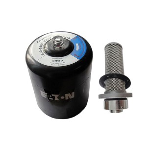
Look closely at the top of the tank and you’ll usually spot a few things mounted directly on it: a level gauge, sometimes a sight glass, a breather or air filter to keep moisture and dust out of the headspace, and often a set of temperature sensors reading the bulk oil condition. Inside, baffle plates divide the tank into sections, forcing returning oil to travel a longer path before reaching the suction side, which helps settle out any air bubbles picked up during circulation.
- Level gauge — tells you at a glance whether oil volume is within the normal operating band
- Breather/air filter — keeps the tank headspace from pulling in contaminated ambient air as oil level fluctuates
- Baffle plates inside — slow the oil down and let air separate out before it’s drawn back into the pumps
Next to the Tank: The Oil Pumps
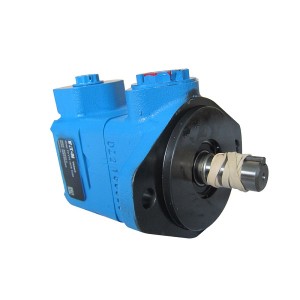
Mounted alongside or partially submerged in the tank, you’ll find the pumps — usually two, sometimes with a third for redundancy, since losing oil pressure on an operating turbine isn’t something anyone wants to risk on a single pump. These are typically screw pumps or vane pumps, chosen for smooth, low-pulsation flow rather than raw output volume.
Each pump has its own motor sitting right on top or beside it, and if you look at the piping immediately downstream of each pump, you’ll usually find a check valve preventing backflow through the idle pump when the other one is running. This is a small detail, but it’s the reason switching between duty and standby pumps doesn’t cause a pressure hiccup in the system.
Why Two Pumps Instead of One Bigger Pump
It might seem simpler to just install one larger pump rather than two smaller ones, but redundancy is really the whole point here. If one pump trips or needs maintenance, the standby unit picks up the load automatically, and the turbine’s EH system never notices the switch happened. A single-pump design would mean any pump fault turns into an oil supply interruption, which isn’t acceptable for a system feeding turbine valve actuators.
The Filtration Section: More Filters Than People Expect
Follow the piping from the pump discharge and you’ll run into filtration almost immediately, usually more than one stage of it. There’s typically a discharge filter right after the pump, catching anything the pump itself might have introduced, and a finer filter further downstream protecting the more sensitive components like servo valves.
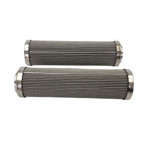
Each filter housing usually has a differential pressure indicator mounted on top or to the side — a small gauge or switch that tells you how loaded the filter element is. On a well-maintained HPU-V100/A, these gauges sit near the low end of their scale. A needle creeping toward the high end is your visual cue that a filter change is coming up.
- Duplex filter housings, where fitted, let you switch to a clean element without shutting down flow — worth locating during a walkdown so you know where the changeover handle is before you actually need it
- Differential pressure gauges or switches on each housing, giving a direct visual or electrical signal of filter loading
- Fine filtration stages positioned closer to the servo valve supply, since that’s where clean oil matters most
The Control Block: Where the Logic Lives
Somewhere on the upper portion of the skid, usually mounted as a fairly compact manifold assembly, sits the control block. This is where directional valves, pressure relief valves, and often the AST and OPC trip solenoids for the broader EH system connect into the main oil supply circuit.
Visually, this section looks the busiest — lots of small valve bodies, wiring conduits running to each solenoid, and pressure gauge ports scattered across the block face. It’s dense, and that density is intentional: consolidating these valves into one machined block reduces the amount of external tubing that would otherwise be needed to connect them individually, which in turn reduces the number of potential leak points across the whole oil supply unit.
The Accumulators: Standing Cylinders Doing Quiet Work
Look for one or more vertical cylindrical vessels mounted near the control block or along the skid frame — these are the hydraulic accumulators. They’re usually painted a distinct color from the rest of the skid, partly for visibility and partly because they’re pressure vessels that need to be easy to identify during inspection.
An accumulator’s job is to store a reserve of pressurized oil, cushioning pressure fluctuations from pump cycling and providing a quick burst of oil volume during fast transient events, like a rapid governor valve movement, without waiting on pump response time alone. Most accumulators on an HPU-V100/A are pre-charged with nitrogen gas on one side of an internal bladder or piston, with hydraulic oil on the other side.
- Gas charging valve, usually near the top of the accumulator body, used to check and adjust nitrogen pre-charge pressure during maintenance
- Isolation valve at the base, allowing the accumulator to be safely isolated and depressurized before any maintenance work
- Pressure gauge, either dedicated to the accumulator or shared with the nearby control block instrumentation
The Oil Cooler: Keeping Everything at Working Temperature
Oil that’s done its job circulating through the EH system comes back warm, sometimes quite warm depending on ambient conditions and system load, and it needs to shed that heat before going back into service. That’s the oil cooler’s job, and depending on the plant’s cooling water availability, it’s typically either a shell-and-tube heat exchanger or an air-cooled fin-tube unit mounted somewhere on or near the skid.
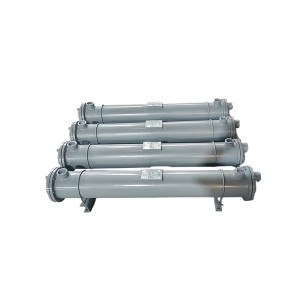
If it’s a water-cooled design, you’ll see cooling water inlet and outlet piping running to the cooler body, often with a temperature control valve modulating water flow based on oil outlet temperature. Air-cooled versions look different — a finned coil section with a fan mounted above or beside it, running whenever oil temperature climbs past a set point.
Putting the Whole Skid Together
Standing back and looking at the full HPU-V100/A as one unit, the layout generally follows a logical flow even if it doesn’t look that way at first glance: oil is drawn from the tank, pushed through the pumps, cleaned through the filtration stages, routed through the control block where directional and safety valves manage where it goes, buffered by the accumulators during transient demand, and cooled before heading back to the tank or out to the turbine’s EH actuators.
| Component | Location on Skid | Primary Function |
|---|---|---|
| Reservoir tank | Base of unit | Oil storage, air separation, heat dissipation |
| Oil pumps | Mounted on or beside tank | Pressurize and circulate oil, redundant duty/standby setup |
| Filters | Downstream of pump discharge | Remove contamination, protect sensitive components |
| Control block | Upper skid area | Directional control, pressure relief, trip valve integration |
| Accumulators | Vertical cylinders near control block | Pressure buffering, transient flow support |
| Oil cooler | Skid perimeter or top | Heat rejection, temperature control |
What to Look For During a Walkdown Inspection
If you’re doing a routine inspection of an oil supply unit like this, a few visual checks don’t take long and tell you a lot:
- Check the tank level gauge and compare it against the normal operating range marked on the sight glass, rather than just glancing and moving on.
- Look at each filter’s differential pressure indicator — a needle sitting near the alarm zone is worth noting even if it hasn’t triggered an alarm yet.
- Listen near the pumps for unusual noise, and check that only the duty pump is running unless a test or transfer is in progress.
- Look for any oil staining around the control block fittings or accumulator base, which can indicate a slow seep worth investigating before it becomes a visible leak.
- Confirm the oil cooler fan (if air-cooled) or cooling water flow (if water-cooled) is actually cycling as expected under current load conditions.
Why Understanding the Layout Actually Helps
Knowing where each component sits on the skid isn’t just useful trivia for a plant tour. When a pressure alarm comes in from the EH system, being able to walk straight to the right filter housing, the right accumulator, or the right section of the control block — instead of tracing pipework from scratch under time pressure — makes troubleshooting considerably faster.
For procurement teams evaluating an HPU-V100/A or a similar EH oil supply unit, having a clear picture of what’s actually inside the skid also helps when comparing quotes or spare parts lists between suppliers, since component layout and quality can vary more than the outer dimensions suggest.
If your plant is planning a new EH oil supply unit installation or reviewing spares for an existing HPU-V100/A, it’s worth requesting the general arrangement drawing directly from the manufacturer — matching that drawing against the physical skid during commissioning makes the whole system a lot less mysterious later on.
Final Thoughts
The HPU-V100/A looks complicated at first glance, and in a sense it is — six or seven major subsystems working together on one skid. But each piece does one clear job: the tank stores and settles oil, the pumps move it, the filters clean it, the control block directs it, the accumulators buffer it, and the cooler keeps its temperature in check.
Once you’ve actually walked around one and traced the piping with your own eyes, the whole unit stops looking like a tangle of pipes and starts looking like exactly what it is — a fairly logical system, laid out to do a specific job reliably for a turbine that depends on it every hour it runs.
Post time: Aug-21-2026
-

EH oil circulating pump oil filter element HC89...
-

Oil purifier filter element P2FX-BH-30X3
-

Hydraulic filter element LH0160D020BN3HC
-

Intelligent Speed monitor HY-TACH
-

Steam turbine actuator oil filter DL004001
-

High Energy Igniter Spark Rod XDZ-F-2990
-

Boiler anti-blocking air pressure sampler PFP-B-II
-

DET Series Displacement Sensors
-

Hydraulic Accumulator NXQ-A-6.3/31.5-L-Y
-

LJB1 type zero sequence current transformer
-

Recycle pump working filter DP1A401EA03V/-W
-

AST solenoid valve Z2805013