

A solenoid directional valve that’s starting to stick doesn’t usually announce itself. The symptoms come gradually — a slightly sluggish actuator response, a pressure transient that’s a bit more pronounced than it used to be, an operation that takes a fraction of a second longer than normal. By the time the fault becomes obvious, it’s often because something downstream has already responded badly to an incomplete valve shift.
The DG4V-3-2AL-M-U-D6-60 solenoid valve is used in steam turbine hydraulic circuits — EH oil systems, jacking oil circuits, and other high-pressure hydraulic control paths — where the valve’s job is to switch oil flow precisely and reliably every time it’s commanded. When the spool stops doing that cleanly, turbine actuator behavior changes in ways that are detectable before they become failures, if you know what to look for.
What Makes This Valve Suited to High-Pressure Turbine Hydraulic Service
The DG4V-3 series is a direct-acting solenoid directional valve — when the solenoid energizes, it moves the spool directly, without a pilot stage in between. That simplicity is one reason it’s used in turbine hydraulic control circuits: fewer components between the electrical command and the hydraulic response means faster, more predictable switching behavior.
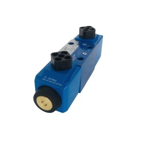
What makes the DG4V-3-2AL-M-U-D6-60 specifically suited to high-pressure, high-frequency switching duty is the way the spool operates within the valve body. The spool moves through the hydraulic fluid rather than through air or a dry bore, and that fluid provides a natural damping effect on spool motion. Even at elevated system pressures and frequent switching cycles, the transition between positions happens smoothly — no hard mechanical impact at the end of travel, no pressure spike from a spool that slams across too fast.
This fluid damping characteristic also means the valve operates quietly. In a turbine hydraulic panel where multiple valves may be switching simultaneously, the absence of mechanical noise from the directional valves makes it easier to detect abnormal sounds from other components — pumps, actuators, check valves — that might otherwise be masked.
The “2AL” configuration is single solenoid with spring return. When the solenoid is energized, the spool shifts to the active position. When it’s de-energized — by command, by a protection signal, or by a power failure — the spring returns the spool to its default position. That default position is deliberately chosen during system design to put connected actuators into a safe state on loss of power. In turbine EH oil systems, this fail-safe logic is typically engineered to close or dump specific control oil circuits when the solenoid drops out.
The Two Failure Modes That Actually Cause Problems
In practice, the faults that cause actuator misbehavior in turbine hydraulic systems trace back to one of two things: spool sticking from contamination, or spring fatigue changing the return force.
Spool Sticking From Contamination
The spool in the DG4V-3-2AL-M-U-D6-60 operates in very tight clearance within the valve bore — typically a few microns. That clearance is tight enough to provide good sealing between ports, but it’s also tight enough that contamination particles at or above that size range can physically wedge the spool and resist movement.
In EH oil systems using phosphate ester fire-resistant fluid, contamination sources include metallic wear particles from system components, varnish and gel deposits from fluid degradation, and fine particulate that bypasses filtration during system disturbances. Any of these can accumulate in the spool clearance over time, initially just increasing the force required to shift the spool, and eventually preventing a full shift or causing the spool to stick partway through travel.
A spool that doesn’t travel its full stroke doesn’t fully open the intended flow path. The actuator receives restricted flow, moves more slowly than commanded, or in a worst case doesn’t move at all. From the DCS or control system perspective, the command was sent and acknowledged — but the actuator response doesn’t match.
Spring Fatigue and Incomplete Return
The return spring in a single-solenoid directional valve is under compression whenever the solenoid is energized, and it cycles through compression and extension every time the valve switches. Over many thousands of cycles, spring fatigue reduces the return force. A weakened spring may not fully return the spool to the default position when the solenoid de-energizes — leaving the spool partway between positions and creating a flow condition that’s neither the commanded active state nor the intended default state.
This is a subtle failure because it only shows up during de-energization. The solenoid energization stroke looks normal — solenoid current, spool travel, actuator response all appear correct. The problem appears when the solenoid drops out and the spool doesn’t return cleanly. In a turbine protection sequence where the valve is expected to return to its safe state rapidly on a trip signal, an incomplete spring return is a serious reliability issue.
Early Warning Through System Pressure Monitoring
The first place to look for early signs of solenoid directional valve degradation isn’t the valve itself — it’s the pressure behavior of the circuit the valve controls.
A valve spool that’s developing sticking resistance takes longer to shift. That delay shows up as a change in the pressure transient pattern at the actuator port. When the valve shifts cleanly, the pressure at the actuator builds or exhausts in a characteristic curve — the shape of that curve is consistent and repeatable in a healthy system. When the spool is dragging, the curve changes: the initial pressure response is slower, there may be a brief plateau where the spool is partially shifted, and the final pressure level takes longer to reach.
In turbine EH oil systems that have pressure transmitters on actuator supply lines — which most modern installations do — this change in transient shape is detectable if you’re trending the data rather than just monitoring for alarm threshold crossings. A system that logged a 150-millisecond actuator pressure build time consistently for months and now shows 220 milliseconds is telling you something changed. That’s the kind of early signal that’s easy to miss if you’re only watching for high/low pressure alarms.
Pressure instability during valve switching is another indicator. A spool that’s sticking partially through its stroke creates a momentary flow restriction that shows up as a pressure spike or dip at the valve outlet. In a clean, well-functioning system, valve switching causes a predictable and smooth pressure transition. Spikes or oscillations during switching — particularly if they’re getting larger over time — point toward spool movement that isn’t smooth.
Using Solenoid Current to Detect Spool Sticking
This is a diagnostic approach that’s underused in plant maintenance but genuinely useful for detecting spool sticking without having to remove the valve from service.
When a DC solenoid coil is energized, the current doesn’t immediately jump to its steady-state value. It rises according to the coil’s electrical time constant, and then — if the solenoid is moving its armature and spool — there’s a brief characteristic dip in the current as the moving armature generates a back-EMF that temporarily opposes the supply voltage. This dip, sometimes called the “pull-in notch” or back-EMF signature, occurs at the moment the armature reaches its end position and the solenoid completes its stroke.
In a healthy DG4V-3-2AL-M-U-D6-60, this current signature is consistent across switching events — the dip occurs at a predictable time after energization and has a characteristic shape. When the spool is sticking, two things change. The current may rise higher than normal initially, because the coil is working against more resistance. The back-EMF dip may be delayed, smaller, or absent — because the armature isn’t completing its travel cleanly or is taking longer to do so.
Measuring this requires either a current clamp and oscilloscope connected to the solenoid supply leads, or a purpose-built solenoid diagnostics tool that captures current waveforms. It’s not a measurement that most maintenance teams set up routinely, but for valves in critical turbine control positions — governing circuit, EH oil system trip paths, jacking oil control — periodic current signature checks during scheduled maintenance windows provide a much more reliable picture of valve condition than a visual inspection or a simple resistance check of the coil.
What to Watch For: Early Warning Indicators
| Indicator | What It Suggests | Action |
|---|---|---|
| Actuator pressure build time increasing over successive operations | Spool travel slowing — possible early contamination sticking | Trend data, increase monitoring frequency |
| Pressure spikes during valve switching that weren’t present before | Spool moving unevenly through partial stroke | Check oil cleanliness, inspect valve at next outage |
| Actuator response slower than commanded on one direction only | Spring return weakening — spring fatigue developing | Test spring return force, plan valve replacement |
| Solenoid current rising higher than baseline before settling | Increased armature resistance — possible spool sticking | Capture current waveform, compare to baseline |
| Back-EMF dip delayed or absent in current waveform | Armature not completing full stroke — spool stuck partway | Remove valve from service, inspect spool and bore |
| Manual override requires noticeably more force than before | Spool friction increasing — contamination in bore clearance | Flush system, replace valve element if force is excessive |
The Manual Override as a Diagnostic Tool
The “M” in the DG4V-3-2AL-M-U-D6-60 part number indicates a manual override — a push-pin on the solenoid end that allows the spool to be shifted manually without energizing the coil. This feature is primarily intended for commissioning and emergency use, but it’s also a quick field diagnostic for spool condition.
On a healthy valve, the manual override pushes in with light, consistent force and the spool snaps back cleanly when released. On a valve with contamination sticking in the bore, the override requires noticeably more force, may feel gritty or inconsistent through its travel, and the spring return may be sluggish when the override is released. This takes about ten seconds to check and gives a reasonable indication of spool condition without any instrumentation.
It won’t detect spring fatigue — the manual override bypasses the spring return by definition. But for a quick check of whether contamination sticking is developing, it’s one of the more practical field diagnostics available without removing the valve.
Oil Cleanliness and Its Connection to Valve Service Life
Most solenoid directional valve faults in turbine hydraulic systems trace back, directly or indirectly, to oil cleanliness. The DG4V-3-2AL-M-U-D6-60 is designed to operate with hydraulic fluid at ISO 4406 cleanliness levels in the range of 16/14/11 or better for reliable service life. Systems running consistently cleaner than this specification tend to see fewer spool sticking incidents and longer intervals between valve replacements.
Systems that have experienced fluid degradation events — overheating, water contamination, a failed filter that allowed a contamination slug through — often show increased valve problems in the months following the event, even after the fluid is partially recovered. The varnish and gel residues from degraded phosphate ester fluid in particular tend to accumulate in spool clearances and are difficult to remove without either flushing the system or replacing the valve.
If solenoid directional valve sticking is becoming a recurring pattern across multiple valves in the same turbine hydraulic circuit, that’s usually a stronger signal about system fluid condition than about the valves themselves. Addressing the root cause — fluid quality, filtration adequacy, or a contamination source — is more effective than replacing valves one at a time.
For procurement teams sourcing replacement DG4V-3-2AL-M-U-D6-60 valves or evaluating equivalent specifications for a turbine hydraulic system, confirming coil voltage, spool configuration, and mounting pattern against the original system design before ordering avoids the kind of compatibility issue that only surfaces during installation. A supplier familiar with turbine hydraulic system components can verify the specification quickly if you provide the system pressure rating and existing sub-plate or manifold details.
Post time: Jul-07-2026
-

EH oil main pump PVH098R01AD30A250000002001AB010A
-

Intelligent Reversal Speed Monitor JM-D-5KF
-

DFSS type steam turbine cylinder sealing grease
-

Generator stator cooling water filter SGLQ-1000A
-

Double gear Pump GPA2-16-16-E-20-R6.3
-

Epoxy-ester air-drying red insulating varnish 9130
-

Limit Switch ZHS40-4-N-03K Inductive Proximity ...
-

Tongma epoxy glass powder mica tape 5440-1
-

Linear variable differential transformer DET200A
-

EH oil main pump discharge filter DP1A601EA01V/-F
-

Generator stator cooling water filter WFF-150-1
-

977HP sealing oil differential pressure valve