

Coal mill hydraulic loading systems don’t give much warning before a pressure problem shows up. The mill is running, the loading cylinder is supposed to be holding the grinding pressure, and then the system either can’t build pressure at all or it builds and bleeds off faster than it should. When that happens in a system using stacked valve assemblies like the MRV-03-B-3-B, the diagnostic question isn’t just “what failed” — it’s “which part of the stack failed,” because the answer changes what you do next.
This article focuses on the MRV-03-B-3-B stackable relief valve as used in coal mill hydraulic stations, the specific failure modes that stacked valve assemblies introduce, and a practical approach to separating inter-layer seal failures from internal spool leakage when the pressure isn’t behaving the way it should.
What the MRV-03-B-3-B Is and Where It Sits in the System
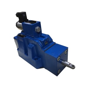
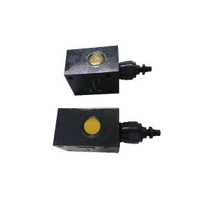
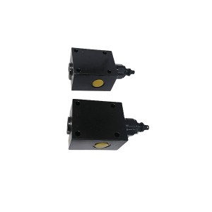
The MRV-03-B-3-B is a modular, stackable relief valve designed for sandwich-plate mounting — it bolts between other valve elements in a manifold stack, with fluid passing through internal porting between layers rather than through external piping. In a coal mill hydraulic loading system, this kind of stacked valve assembly controls and limits the pressure in the loading circuit, which determines how hard the grinding rollers press against the grinding table.
The stacking arrangement is space-efficient and keeps the valve circuit compact, which suits the installation constraints of most mill hydraulic stations. But it introduces a failure mode that single-body valves don’t have: the inter-layer interfaces. Each joint between valve plates is sealed by O-rings sitting in machined grooves, and those O-rings carry the full system pressure. If they degrade, age out, or were installed incorrectly, internal leakage between layers can cause pressure loss that looks from the outside exactly like a valve spool problem.
Getting that distinction right early saves a lot of unnecessary disassembly.
Two Different Problems, Same Symptom
When a coal mill hydraulic system can’t build pressure to the loading setpoint, or holds pressure for a while and then bleeds off gradually, there are two primary internal leakage sources to consider in a stacked valve assembly like this one.
The first is inter-layer seal leakage — the O-rings between valve plates have failed, aged, or weren’t seated properly during assembly. Oil is bypassing between layers internally, either crossing from high-pressure to low-pressure porting within the stack, or leaking to the return circuit at a junction that should be sealed.
The second is valve spool leakage — the relief valve element itself isn’t seating cleanly. Oil is bypassing across the spool seat and returning to tank even when the system pressure is below the cracking point. This can happen because of contamination holding the spool off its seat, spool wear, or damage to the seating surface.
Both produce the same observable result at the system level: pressure that doesn’t build properly, or a loading cylinder that loses pressure faster than the leak-down specification allows. The distinction matters because the fix is completely different. O-ring failure means disassembling the stack, inspecting and replacing the inter-layer seals, and reassembling with correct installation. Spool leakage means either cleaning the valve, replacing the spool assembly, or replacing the entire valve element.
Why O-Ring Failure Is More Common Than It Gets Credit For
In a well-maintained system with clean oil and stable temperatures, the O-rings in a stacked valve assembly can last a long time. But coal mill hydraulic environments aren’t always ideal. Temperature cycling as the mill starts and stops puts thermal stress on elastomer seals. Hydraulic fluid that’s run hot or accumulated contamination degrades O-ring materials faster than clean, temperature-controlled fluid would.
Installation is the other factor. O-rings in inter-layer positions can be pinched, twisted, or seated in the wrong groove during assembly — problems that aren’t visible once the stack is bolted together and can produce immediate leakage or early failure. Any time the valve stack has been disassembled and reassembled — during a previous maintenance intervention, during installation, or after a system modification — the inter-layer seals should be treated as a potential source of leakage until confirmed otherwise.
O-ring material matters too. Standard NBR O-rings work fine with mineral hydraulic oil under normal temperature conditions. If the mill hydraulic station uses a different fluid type, or if the operating temperature regularly runs higher than NBR is rated for, seal degradation will accelerate. Specifying the correct O-ring material for the actual operating conditions is one of those details that gets overlooked and shows up as repeated seal failures.
How to Separate the Two Failure Modes — A Step-by-Step Approach
The goal of the diagnostic process is to isolate where the leakage is occurring without doing more disassembly than necessary. Working through the following steps in order generally gets to the answer without unnecessary teardown.
Step 1: Confirm the Leakage Is Internal, Not External
Before assuming internal leakage, do a quick check of all external connections on the valve stack — port connections, mounting bolts, and any visible O-ring faces at the stack perimeter. External leakage from loose connections or a damaged face seal can mimic internal pressure loss symptoms and is easier to find and fix than either of the internal failure modes.
If there’s no visible external leakage and the system is losing pressure internally, move on.
Step 2: Check the Return Line Flow During Pressure Hold
With the mill in a static pressure-hold condition — pump off, loading cylinder at target pressure — observe the return line flow at the tank or through a flow indicator if one is installed. Any significant flow returning to tank while the pump is off and no actuator is moving indicates internal bypassing somewhere in the circuit.
This doesn’t yet tell you whether it’s the O-rings or the spool, but it confirms the leakage is happening across a pressure boundary rather than being a gauge or transducer issue.
Step 3: Isolate the Valve Stack From the Rest of the Circuit
If isolation valves allow it, isolate the MRV-03-B-3-B stack from the loading cylinder and measure how quickly pressure decays on the cylinder side alone with the stack blocked off. Then do the reverse — hold pressure on the valve stack inlet side and monitor decay there.
Pressure decaying on the cylinder side with the stack isolated points to cylinder seal leakage, not the valve. Pressure decaying on the valve stack side with the cylinder isolated points to leakage within or through the valve assembly.
Step 4: Distinguish O-Ring Leakage From Spool Leakage
This is the key step. If leakage is confirmed within the valve stack, the question is which type it is.
O-ring inter-layer leakage typically shows up as leakage between specific porting paths — for example, pressure oil crossing to a return port internally at a layer junction. If the valve stack has intermediate pressure test points between layers (not always present, but worth checking the manifold design for), you can identify which interface is leaking by monitoring pressure at each point during a hold test.
Spool leakage in a relief valve follows the path from high-pressure inlet across the spool seat to the return port. One practical check: if you can temporarily increase system pressure slightly above the normal operating point while monitoring return flow, spool leakage will increase proportionally with pressure differential across the spool. O-ring leakage between layers may not respond in the same way, depending on which ports are affected by the failed seal.
Another useful indicator is leakage temperature. Oil that’s bypassing across a valve spool under significant pressure differential will be warmer than surrounding oil — this can sometimes be detected by touch or with a contact thermometer on the return line immediately downstream of the valve, versus the general return oil temperature. Inter-layer O-ring leakage crossing between adjacent ports at lower differential pressure may not show the same temperature signature.
Step 5: Inspect the O-Rings During Disassembly
If the above steps point toward inter-layer seal failure, the stack needs to come apart. When it does, inspect each O-ring systematically before assuming any of them are fine. Look for:
- Flattening or compression set — the O-ring has taken a permanent deformation and no longer has enough resilience to maintain a seal under pressure cycling
- Surface cracking or hardening — signs of thermal or chemical degradation from the hydraulic fluid or operating temperature
- Twisting or misalignment in the groove — a sign of installation error rather than in-service failure
- Extrusion into adjacent clearances — O-ring material that’s been forced into the gap between plates under high pressure, indicating the O-ring was undersized or the clearance was too large for the operating pressure
Replace all inter-layer O-rings as a set when reassembling — not just the ones that show visible damage. An O-ring that looks acceptable but has been in service alongside a failed one has experienced the same operating history and is likely close to the same failure point.
Quick Reference: Leakage Source Identification
| Observation | More Likely Cause | First Action |
|---|---|---|
| Pressure decays slowly during hold, no return flow visible | Minor spool wear or seat contamination | Clean valve spool and seat, retest |
| Significant return flow with pump off and cylinder isolated | Spool leakage across relief valve seat | Inspect and clean spool; replace if worn |
| Pressure loss varies inconsistently, not proportional to system pressure | Inter-layer O-ring failure — path-dependent leakage | Disassemble stack, inspect all O-rings |
| Return line warm locally at valve stack, not at cylinder | Spool leakage generating heat across pressure drop | Inspect relief valve spool and seating surface |
| Problem appeared after recent maintenance or reassembly | O-ring installation error | Re-disassemble stack, replace all inter-layer seals |
| Pressure loss worsened after fluid temperature increase | O-ring thermal degradation | Check O-ring material compatibility with operating temperature |
A Few Things Worth Getting Right During Reassembly
Once you’ve identified and addressed the leakage source, reassembly of the stacked valve requires more care than it sometimes gets. The mounting bolt torque sequence matters — uneven torque across the stack distorts the mating faces and can cause O-rings to seal unevenly or not at all. Follow the manufacturer’s torque specification and sequence, and use a calibrated torque wrench rather than estimating by feel.
O-ring lubrication during installation is worth doing correctly. A light coat of clean hydraulic fluid or O-ring assembly lubricant compatible with the seal material helps the O-ring seat into its groove without twisting during plate assembly. Dry installation of O-rings in tight grooves frequently causes the twist that shows up as immediate leakage once pressure is applied.
After reassembly, bring the system up to pressure slowly and hold at intermediate pressure steps before going to full operating pressure. This lets any marginal seals show their condition at lower load rather than failing immediately at full pressure when the mill is back in service.
Sourcing Replacement Parts
For the MRV-03-B-3-B specifically, replacement O-ring kits should be sourced to match the original seal material specification — not just the physical dimensions. If the original installation used NBR seals and the system has since been converted to a different fluid, or if operating temperatures have changed, the replacement seal material needs to reflect the current conditions rather than the original specification.
If you’re sourcing replacement valve elements or seal kits for a coal mill hydraulic station and want to confirm the correct specification for your specific application, a supplier with experience in mill hydraulic system components can usually verify material compatibility and dimensional fit quickly from the valve model and system fluid details.
Pressure problems in mill hydraulic stations tend to get worse rather than better on their own. Working through a systematic diagnostic process — rather than replacing parts based on the most accessible component — saves time and gets the mill back online faster with a confirmed fix rather than a temporary patch.
Post time: Jul-06-2026
-

Needle Valve DN40 PN35
-

Steam turbine Shutoff valve HF02-02-01Y
-

DN80 Sealing oil vacuum tank floating valve
-

Double gear Pump GPA2-16-16-E-20-R6.3
-

High Temperature cylinder sealing grease MFZ-3
-

Ultrasonic Level Meter Probe CEL-3581F/G
-

EH Oil Actuator Filter QTL-6021A
-

DC Vertical lubricating oil pump 125LY-23-4
-

Magneto electric Rotation Speed Sensor ZS-02
-

EH oil pump discharge filter AP1E101-01D03V/-WF
-

Actuator Inlet Flushing Oil Filter DP301EA01V/-F
-

DF9011 Pro Precision Transient Rotational Speed...