

Six solenoid valves, one block of machined steel, and a system of internal passages that decide whether a turbine’s steam valves are allowed to open at all. That’s the 0508.919T0301.AW001 in one sentence. Four AST valves. Two OPC valves. No external tubing between them — everything routes through drilled channels inside the manifold body itself.
Field engineers rarely get a clear picture of what’s happening inside this block. The valves mount on the outside, the pressure gauges tell you what’s happening at the ports, but the actual path oil takes between “solenoid energized” and “trip oil pressure established” stays hidden unless someone draws it out. So let’s draw it out.
Two Valve Families, Two Different Jobs
AST stands for Autostop — these four valves are the ones responsible for dumping trip oil pressure fast when the turbine needs to shut down. OPC stands for Overspeed Protection Control — these two valves handle a faster-acting, lower-volume trip path specifically tuned for overspeed events, separate from the main autostop function.
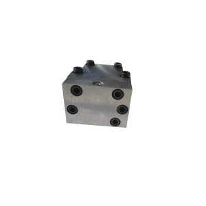
Both valve types live on the same manifold block, sharing the same body but not the same oil channels. Keeping them physically integrated but functionally separate is really the whole design philosophy behind this manifold. One casting, two independent protective paths.
Why Four AST Valves Instead of One
A single trip valve is a single point of failure. If a plant wants genuine redundancy in the trip function — meaning no one component failure, whether it fails open or fails closed, can either falsely trip the turbine or fail to trip when it should — one valve just doesn’t cut it.
Four valves arranged in a 2-out-of-4 or similar voting configuration solves this. The exact voting logic depends on the specific turbine control philosophy, but the general idea holds across most designs using this manifold: enough valves must actuate together to confirm a real trip signal, while a single stuck or failed valve doesn’t compromise the whole system either way.
Series and Parallel Arrangement Inside the Block
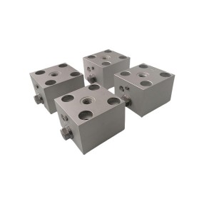
Here’s where the internal oil channels do their work. The four AST valves aren’t simply four parallel drains from a single chamber. Instead, they’re arranged so that certain valve pairs are connected in series along one oil path, while that pair sits in parallel with a second pair on a separate path.
Think of it as two independent series-pairs, working in parallel with each other. For trip oil pressure to drop through one path, both valves in that series-pair need to open. But because there are two such paths running in parallel, either path opening is enough to drop overall trip pressure and initiate a trip.
- This means a single valve failing to close (staying open) doesn’t fully dump trip oil on its own, because its series partner in that path is still blocking flow — protecting against a false trip from one stuck-open valve.
- It also means a single valve failing to open (staying closed) during an actual trip demand doesn’t prevent the trip, because the parallel path with its own series-pair can still complete the drain — protecting against a failed trip from one stuck-closed valve.
This 2×2 series-parallel layout inside the manifold is what gives the AST section its fault tolerance. The machined channels connecting these four valve ports are what make that logic physical rather than something handled purely by external wiring and control logic.
| Configuration | Behavior |
|---|---|
| Series pair (within one path) | Both valves must open together to drain that path’s oil |
| Parallel paths (two series pairs) | Either path draining is sufficient to complete the trip |
| Single valve failure, stuck open | Series partner still blocks flow — no false trip from this alone |
| Single valve failure, stuck closed | Parallel path still available — trip function preserved |
The OPC Valves — A Separate, Faster Path
The two OPC valves don’t follow the same series-parallel voting logic as the AST section. Their job is narrower and more speed-focused — reacting to overspeed conditions and modulating or dumping a smaller oil volume specifically tied to governor valve control, rather than the full autostop trip function.
Because this is a two-valve arrangement rather than four, the internal channel routing is simpler, typically just parallel paths feeding a shared drain gallery. Response time matters more here than redundancy depth, since overspeed protection needs to act within a narrow window before shaft speed climbs too far.
Building Trip Oil Pressure — What “Resetting the Trip” Actually Means Inside the Block
The Chinese term for this, 挂闸 (literally “hanging the latch”), refers to the reset action that re-establishes trip oil pressure after a trip event, or during initial startup before the turbine is allowed to run. Understanding what happens inside the manifold during this reset helps explain why the whole system works the way it does.
When the reset action occurs, high-pressure control oil is admitted into the manifold’s supply gallery. With all AST valves in their closed (non-tripping) position, oil pressure builds through the internal channels and pressurizes the trip oil header that feeds the steam valve actuators.
Step by Step Through the Reset Sequence
- High-pressure oil enters the manifold’s main supply port, filling the internal gallery that feeds all four AST valve chambers.
- With the AST valves de-energized in their closed position (blocking the drain path), oil cannot escape through either of the two series-parallel drain paths described earlier.
- Pressure builds and stabilizes in the trip oil circuit, which extends out from the manifold to the steam valve actuators governing HP, IP, and other steam admission valves.
- Once trip oil pressure reaches its normal operating value, the associated steam valves are mechanically or hydraulically permitted to open — the trip oil pressure itself acts as the “permission” signal these valves need before they can move off their seats.
- The OPC valves, in their normal closed position during this sequence, don’t interfere with trip oil buildup, since their circuit handles a separate, smaller oil path tied to overspeed response rather than the main trip header.
Until this pressure is fully established, the steam valves physically cannot open, regardless of what the control system or operator wants. That’s the entire point of a hydraulic trip system built this way — the permission to open isn’t a digital signal that can be spoofed or bypassed, it’s an actual physical oil pressure that has to be real and present.
Why This Design Matters for Steam Turbine Control Reliability
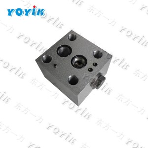
A manifold block like the 0508.919T0301.AW001 consolidates what would otherwise be a sprawling network of external tubing, fittings, and individual valve bodies into a single machined component. Fewer external joints means fewer places for a high-pressure oil leak to develop, and a more compact footprint near the turbine front standard where space is often tight.
But the real value isn’t just mechanical tidiness. It’s that the fault-tolerant series-parallel logic for the AST valves is built into the physical oil channels themselves, not just programmed into a control system that could have its own separate failure modes. A hydraulic system behaves according to physics, not software, and that’s a meaningful distinction for a protection function this critical.
Practical Notes for Maintenance and Procurement Teams
A few things worth keeping in mind when working with this type of integrated manifold block:
- Internal channel layout is specific to this manifold design — don’t assume a replacement block from a different manufacturer shares the same series-parallel voting arrangement without confirming it against documentation.
- When troubleshooting a trip event, checking which specific AST valve pair failed to seal, rather than just noting “a trip occurred,” helps determine whether the fault tolerance design actually functioned as intended or whether both paths were compromised simultaneously.
- During overhaul work involving manifold removal, internal passages should be inspected for varnish buildup or contamination, since blocked internal channels can silently defeat the redundancy this design depends on.
If your plant is planning a manifold block inspection or replacement as part of turbine control system maintenance, it’s worth requesting the internal oil circuit schematic for the 0508.919T0301.AW001 specifically, rather than relying on a generic AST/OPC layout that may not match the actual series-parallel configuration inside this particular block.
Closing Thoughts
The 0508.919T0301.AW001 packs a fair amount of protective logic into a single piece of machined steel. Four AST valves working in a fault-tolerant series-parallel arrangement, two OPC valves handling a faster overspeed path, and internal channels that turn a reset action into a physical, verifiable trip oil pressure — all without a single external tube connecting one valve to the next.
Understanding that internal layout isn’t just academic. It’s what makes troubleshooting faster and more accurate when something does go wrong, and it’s a good reminder that in steam turbine control, the most critical safety logic sometimes lives inside a block of drilled steel rather than a line of code.
Post time: Aug-20-2026
-

LVDT sensor TD series Armored cable LVDT sensor...
-

Oil purifier circulating filter element HC8314F...
-

Blind-free two-color water meter B69H-32/2-W
-

Hydraulic lubricating oil station filter ZNGL02...
-

Magnetic Liquid Level Indicator UHZ-519C
-

Actuator Inlet Flushing Oil Filter DP301EA01V/-F
-

AST solenoid valve Z2805013
-

EH Oil Actuator Filter QTL-6021A
-

HTD series LVDT displacement actuator position ...
-

Magneto electric Rotation Speed Sensor ZS-02
-

Electro-hydraulic servo valve G761-3034B
-

Hydraulic oil return filter element CRA110CD1