

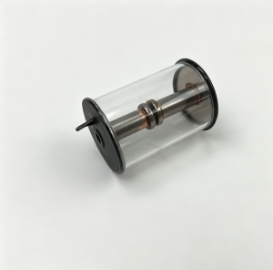
The XDH8-80C Spark Gap Tube is the high-voltage switching element at the heart of the XDH series high-energy ignition device. When the storage capacitor charges to the spark gap tube’s breakdown threshold, the gas inside ionizes, a conductive channel forms, and the stored energy releases in a pulse that travels through the shielded cable to the semiconductor spark plug at the burner tip. The whole sequence happens in microseconds. Whether it happens reliably — and whether the spark gap tube survives to do it thousands of times more — depends partly on two installation details that get less attention than they should: the orientation the tube is mounted in, and the quality of the ignitor’s ground connection.
Does Installation Orientation Affect the Spark Gap Tube?
The XDH series high-energy ignitor can be mounted horizontally or vertically — the device as a whole is designed to work in either orientation when properly secured. The question of whether the spark discharge tube inside it cares about which way it’s pointed is worth answering directly.
For gas-filled spark gap switches like the XDH8-80C, the discharge physics depend on the gas pressure, electrode geometry, and the electric field distribution between the electrodes. None of these are significantly affected by gravity at the scale of a device this size. The breakdown voltage and discharge characteristics of the tube don’t change with orientation in any meaningful way under normal operating conditions.
That said, there’s a practical consideration that comes up with some gas-filled discharge tubes: if the tube contains any liquid component — such as a liquid-gas mixture used in certain tube designs to improve consistency — then orientation can affect how that liquid distributes across the electrode surfaces and alter discharge behavior. For the XDH8-80C specifically, the tube is a sealed gas discharge device without liquid components, so this concern doesn’t apply.
When replacing the spark gap tube, orientation during installation doesn’t need special attention from a discharge performance standpoint. What does matter is that the tube seats properly in its socket or mounting, makes clean electrical contact at both terminals, and is secured so vibration from the combustion system can’t work it loose over time. A tube that’s physically loose in its mount — regardless of orientation — will develop intermittent contact that shows up as inconsistent ignition or premature tube failure.
What Grounding Actually Does in a High-Energy Ignition Circuit
High-energy ignition systems operate at voltages that most industrial electrical equipment doesn’t approach. The capacitor in a unit like the XDH series charges to several kilovolts before the spark gap tube fires. The discharge current pulse, though brief, is substantial. The return path for that current — back through the shielded cable, through the ignitor body, and to ground — needs to be a low-impedance path for the system to work as designed.
Ground in this context isn’t just a safety measure. It’s an active part of the discharge circuit. The energy stored in the capacitor releases through a loop: capacitor → spark gap tube → shielded cable → spark plug → burner ground → cable shield → ignitor chassis → earth ground → back to capacitor. Any significant resistance or impedance anywhere in that loop reduces the peak current the spark plug receives and changes the character of the discharge.
A correctly grounded ignitor with a proper earth connection has a low-impedance return path. The full stored energy reaches the spark plug as a high-amplitude, fast-rise pulse — the kind that reliably ignites atomized fuel. A poorly grounded ignitor forces the discharge current through a higher-impedance path. Peak current drops, the pulse spreads out in time, and the effective spark energy at the plug tip is lower than the capacitor’s stored energy would suggest.
What Poor Grounding Does to the Ignitor Internally
Reduced spark energy at the plug tip is one consequence of poor grounding. The less obvious consequence is what happens inside the ignitor itself when the discharge return path is compromised.
When the ground impedance is high, the discharge current has to find an alternative return path. At the voltages involved in a high-energy ignition system, current will find a path — through stray capacitance, through nearby conductors not intended to carry discharge current, or through the insulation of internal components that are now seeing a voltage difference they weren’t designed for. This is how poor grounding causes internal component damage that has nothing obvious to do with the ground connection itself. Insulation breakdown, carbonization tracks on internal surfaces, and premature failure of the spark gap tube or the capacitor can all result from repeated high-voltage discharges through a poorly defined return path.
In a boiler combustion system where the ignitor fires repeatedly during each light-off sequence, the cumulative stress from poor grounding adds up. The ignitor may work initially — the discharge still occurs, the spark still fires, the burner still lights — but component life is shortened, and the degradation is happening invisibly between light-off events.
How to Verify Grounding Reliability in the Field
Verifying that the ignitor ground is actually reliable — not just connected — requires a few specific checks that go beyond confirming a wire is attached.
Resistance Measurement
With the ignitor de-energized and isolated from the electrical supply, measure the resistance from the ignitor chassis ground terminal to the plant earthing system using a low-resistance ohmmeter. The acceptable value depends on the system specification, but for a high-voltage discharge device the ground resistance should be well below 1 ohm — ideally below 0.5 ohm. Values above 1 ohm indicate connection problems that need correction before the ignitor is used.
Measure at the farthest point in the ground chain, not just at the first connection. A ground wire with a corroded lug at the plant earthing bar end may show low resistance at the ignitor chassis terminal but high resistance at the actual earth connection.
Visual Inspection of the Ground Path
Check every connection in the grounding chain physically. The ignitor chassis to ground wire connection, the ground wire itself along its full run, and the earth bar connection at the plant end. Look for:
- Corroded or loose cable lugs at either end — corrosion increases contact resistance significantly, even when the connection looks secure
- Ground wire that’s been routed alongside high-voltage cables — induced interference can affect the discharge circuit
- Ground wire that’s too small in cross-section for the discharge current involved — undersized ground conductors have higher resistance and may not be rated for the transient currents in a high-energy ignition discharge
- Any splice or junction in the ground wire — each additional connection is a potential high-resistance point
Checking Cable Shield Continuity
The shielded cable between the ignitor and the spark plug carries the discharge and its return. The shield is part of the return current path and needs to be continuous and properly terminated at both ends. Measure shield continuity from the ignitor end to the plug end and verify the termination at both ends is solid. A shield that’s open-circuit at one end or poorly terminated at the connector body is effectively removing part of the discharge return path.
Installation and Grounding Reference
| Aspect | Requirement or Check | Common Problem |
|---|---|---|
| Spark gap tube orientation | No specific orientation requirement for XDH8-80C | Loose seating in mount causing intermittent contact |
| Tube installation | Firm seating, clean terminal contact, secured against vibration | Vibration-induced loosening in combustion system environment |
| Ground resistance | Below 0.5 ohm chassis-to-earth; measure full path | Corroded lugs giving false low reading at chassis, high resistance at earth bar |
| Ground wire condition | Correct cross-section, continuous run, no splices | Undersized wire, corroded splice adding resistance |
| Cable shield continuity | Continuous shield, properly terminated both ends | Shield open or poorly crimped at connector body |
| Verification frequency | Check at each planned maintenance interval and after any cable work | Ground resistance not checked after reconnection following maintenance |
When to Suspect a Grounding Problem
Inconsistent ignition — the burner lights on some attempts but not others with no change in fuel conditions — is one of the first operational signs of a grounding problem in a high-energy ignitor. If the spark gap tube and spark plug have been checked and are in good condition, and ignition is still unreliable, the ground path is worth investigating before replacing more components.
A ignitor that’s showing signs of internal component stress — unusually short spark gap tube life, burn marks around internal connections, or an acrid smell after firing — is likely discharging through unintended paths, which points toward inadequate grounding as a contributing factor.
After any maintenance work that involves disconnecting or reconnecting the ground connection, or replacing the shielded cable, the ground resistance should be measured and verified before the ignitor is returned to service. It’s a five-minute check that confirms the discharge circuit return path is correct before the next light-off attempt.
For plants sourcing XDH8-80C replacement spark gap tubes or reviewing ignition system maintenance procedures, having the ground resistance specification from the ignitor manufacturer’s documentation on hand ensures the field verification is being done to the correct standard rather than an assumed value.
Summary
The XDH8-80C spark gap tube doesn’t require specific orientation during installation — its discharge characteristics are the same horizontal or vertical. What matters at installation is that it seats properly, makes clean terminal contact, and is secured against vibration. Grounding is a different matter entirely. Poor grounding doesn’t just create a safety issue — it reduces the effective spark energy reaching the plug tip and forces discharge current through paths inside the ignitor that aren’t designed to carry it, shortening component life in ways that aren’t immediately obvious. Measuring ground resistance through the full grounding path, inspecting the cable shield, and verifying both after any maintenance work are the checks that keep the ignition system working reliably across its full service life.
Post time: Aug-03-2026
-

EH Oil Main Pump Discharge Oil Filter Element D...
-

MM2XP 2-pole 24VDC Digital Power Intermediate R...
-

Regeneration device anion filter AZ3E303-05D01V/-W
-

WTYY series Bimetal Thermometer Temperature Gauge
-

lubricating oil filter element 2-5685-0154-99
-

EH oil circulating pump oil filter element HC89...
-

Filter element QF1D350CJJHC
-

Ultrasonic Level Meter Probe CEL-3581F/G
-

LVDT Position Sensor HTD-100-3
-

EH oil main pump PVH074R01AB10A250000002001AE010A
-

Stainless steel globe throttle check valve LJC ...
-

FY-40 floating valve of Generator seal oil floa...