

Loss of lubricating oil supply to a steam turbine bearing isn’t a situation that gives much warning. The oil film that keeps the shaft journal from contacting the bearing surface collapses within seconds of flow interruption, and bearing damage begins almost immediately. That’s why the protection system around the turbine lube oil circuit matters — not just whether it has protection, but how that protection is structured and what happens when one element in the chain doesn’t work.
The ZNJC09010101 is an industrial-grade flow switch used for lubricating oil flow monitoring in steam turbine lube oil systems. Understanding its specific role in the protection logic — and what the system relies on if that flow switch develops a fault — is practical information for anyone responsible for turbine protection system maintenance or design.
How Flow Switches Fit Into Lube Oil Protection
Steam turbine lubricating oil systems typically use multiple parameters to monitor bearing supply condition. Oil pressure at the main header is the most common primary measurement — it’s continuously monitored, and low pressure triggers both alarms and protective actions including auxiliary pump startup and, at sufficiently low pressure, turbine trip. Flow measurement at individual bearing supply lines adds another layer of information that header pressure alone doesn’t provide.
A flow switch like the ZNJC09010101, installed in a bearing supply branch, detects whether oil is actually moving through that specific line to that specific bearing. This matters because header pressure can look acceptable while a blocked or damaged individual supply line leaves one bearing without oil. The pressure measurement upstream of the blockage doesn’t see the problem. A flow switch downstream of it does.
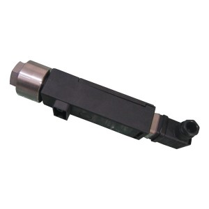
In most turbine lube oil protection architectures, the flow switch in a bearing branch line serves as a supplementary monitoring signal rather than the sole trip-initiating element. The primary protection action — turbine trip — is usually driven by oil header pressure falling below a defined threshold, because pressure is a more reliable, continuously variable measurement that integrates across the whole circuit. The flow switch provides confirmation and early warning at the individual bearing level, and its signal typically feeds into alarm logic and operator indication before or alongside protective action.
That said, the specific role of any flow switch in a given protection system depends entirely on how the protection logic was designed for that installation. In some configurations, a bearing branch flow switch output is directly wired into the trip logic. In others it generates an alarm only. Checking the plant’s protection logic documentation — the relay logic diagram or DCS protection function block — is the only way to know with certainty what the ZNJC09010101 is configured to do in a specific installation.
What Happens If the Flow Switch Fails
A flow switch can fail in two directions. It can fail to actuate when flow actually drops — a stuck-closed contact that doesn’t change state when oil stops flowing. Or it can actuate when flow is normal — a spurious output that generates a false alarm or, if wired to trip logic, a false trip.
The first failure mode is the more serious one from a protection standpoint. If the ZNJC09010101 fails to send a low-flow signal when bearing oil supply actually drops, whatever protection that signal was supposed to initiate doesn’t happen. The question then is what else in the system detects the same condition.
This is where the layered nature of turbine protection design matters. A properly designed turbine protection system doesn’t rely on a single element for bearing protection. Several independent measurements cover overlapping failure scenarios:
- Lube oil header pressure — the primary continuous measurement. A pressure drop that affects the bearing in question will show at the header. If the flow switch fails, header pressure low alarm and trip remain active. The gap is specifically the scenario where only one bearing branch is affected while header pressure stays normal — which is the scenario the branch flow switch was meant to catch.
- Bearing metal temperature — thermocouples or RTDs embedded in the bearing housing detect the temperature rise that begins when the oil film is compromised. Response is slower than a flow switch — it takes time for the bearing metal to heat measurably after oil loss — but it provides independent confirmation that a problem exists. High bearing temperature alarm and trip setpoints are standard in turbine protection systems.
- Bearing vibration — shaft vibration increases when bearing lubrication is inadequate. Vibration monitoring (shaft vibration via proximity probes and bearing housing vibration via seismic sensors) provides another independent indicator. Vibration-based protection typically has alarm and trip setpoints that respond to the mechanical changes that accompany bearing distress, including those caused by oil film breakdown.
- Axial displacement — in some failure scenarios, loss of oil at a thrust bearing affects axial position. Axial displacement monitoring provides protection against thrust bearing overload.
The Time Gap Problem
The honest assessment of backup protection is that it works, but it introduces a time delay compared to flow-based detection. A flow switch that detects oil loss responds essentially immediately — it changes state when flow drops below the setpoint, which happens within seconds of oil supply interruption. Bearing temperature-based protection waits for the bearing metal to heat up. Vibration-based protection waits for the mechanical deterioration to produce measurable vibration change.
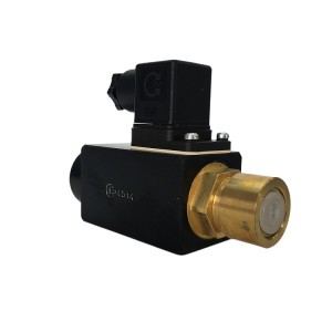
For a turbine bearing, the difference between immediate detection and detection after 30 to 60 seconds of oil starvation is significant. Bearing damage can be extensive by the time temperature or vibration signals reach alarm thresholds. The flow switch’s value in the protection chain is precisely this speed advantage — it detects the cause before the effect becomes measurable.
This is why a failed flow switch isn’t a situation to note and defer. The backup protection systems will eventually catch a bearing oil loss event, but they’ll catch it later, with more bearing damage already done. Maintaining the flow switch in working order keeps the fastest layer of bearing protection active.
Protection Layer Comparison
| Protection Element | What It Detects | Response Speed | Covers Single-Branch Blockage? |
|---|---|---|---|
| Lube oil header pressure | System-wide pressure loss | Fast — continuous analog signal | No — won’t see isolated branch blockage |
| Bearing branch flow switch (ZNJC09010101) | Flow loss at specific bearing | Fast — responds to flow drop directly | Yes — installed per bearing branch |
| Bearing metal temperature | Thermal effect of lubrication loss | Slower — requires heat accumulation | Yes — per-bearing measurement |
| Bearing/shaft vibration | Mechanical effects of bearing distress | Slower — requires vibration development | Yes — per-bearing or per-shaft section |
| Axial displacement | Thrust bearing overload | Moderate — responds to rotor movement | Partially — thrust bearing specific |
Testing and Maintaining the Flow Switch
A flow switch that’s installed and never tested is a flow switch of unknown reliability. The ZNJC09010101, like any switching device in a protection system, needs periodic functional testing to confirm it actuates correctly at its setpoint and returns to normal state when flow is restored.
Testing a bearing branch flow switch typically requires temporarily reducing flow through the branch to below the switch setpoint — either by throttling the supply valve while monitoring the output, or by using a test bypass if the installation includes one. The switch output should change state at the configured setpoint flow. Reconnect to normal flow and confirm the switch resets. Record the test result and date.
The testing interval should be defined in the plant’s turbine protection system maintenance program. For protection devices on critical equipment, annual testing at minimum is common practice, with testing also performed after any maintenance work on the flow switch or its connected piping.
A flow switch that fails its functional test — either doesn’t actuate at setpoint, doesn’t reset reliably, or shows intermittent output — should be replaced promptly. Operating with a known-failed flow switch in a bearing protection circuit means accepting reduced protection with full awareness of what’s been removed from the system.
Practical Notes on Flow Switch Replacement
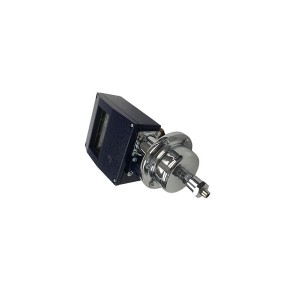
When replacing the ZNJC09010101 or selecting a replacement for an existing installation, a few specifications matter beyond just the part number. The switch setpoint — the flow rate at which the output changes state — needs to match the original calibration for the specific bearing branch. A replacement with a different setpoint may actuate too early (causing nuisance trips or alarms at normal flow) or too late (missing actual flow loss events).
The switch’s contact type and rating also need to match the protection logic it connects to. A normally-open contact wired into a fail-safe trip circuit behaves differently from a normally-closed contact in the same circuit. Verify contact configuration against the protection logic diagram before installation.
For plants reviewing their turbine lubricating oil protection system configuration or sourcing replacement flow switches, working from the original protection design documentation ensures the replacement maintains the protection intent rather than just the physical connection.
The Short Version
The ZNJC09010101 flow switch in a turbine lube oil system typically serves as a fast-response monitoring element for individual bearing oil supply — catching the specific scenario where a single branch loses flow while header pressure stays normal. Whether it’s wired to trip logic or alarm-only depends on the specific installation. If it fails, backup protection from bearing temperature and vibration monitoring still covers a real oil loss event, but responds more slowly and with more bearing damage already done before the signal arrives. Keeping the flow switch functional and testing it periodically maintains the fastest layer of bearing protection in the system.
Post time: Aug-04-2026
-

Platinum Resistor Temperature Sensor WZPM-201
-

Jacking oil pump filter element HBX-250×10
-

23D-63B steam turbine turning solenoid valve
-

OPC solenoid valve 4WE6D62/EG220N9K4/V
-

High Pressure Welding Angle Globe Valve J64Y-64
-

Double gear Pump GPA2-16-16-E-20-R6.3
-

Steam Turbine Excitation System CPU board PCA-6...
-

TDZ-1E series linear displacement transducer LV...
-

EH oil circulating pump oil filter element HC89...
-

High resistance anti corona paint DFCJ1018
-

Jacking Oil System Backwash Filter ZCL-I-450
-

EH oil actuator filter DP6SH201EA03V/-W for Ste...