

Direct-acting relief valves don’t get much attention until something goes wrong. They sit in the hydraulic circuit, do their job quietly, and most maintenance teams only think about them when a pressure alarm shows up or the system starts behaving oddly. The DBDS20K10/315 is that kind of valve — reliable under normal conditions, but with a known long-term issue that’s worth understanding before it shows up as an operational problem.
That issue is spring relaxation. Over time, the spring inside a direct-acting relief valve loses some of its preload, and the set pressure drifts downward. How much it drifts, how fast, and what to actually do about it in a working power plant — that’s what this article covers.
What’s Actually Happening Inside the Valve
The DBDS20K10/315 direct-acting relief valve works on a straightforward principle. System pressure pushes directly on a conical valve element. A spring pushes back. When the hydraulic force exceeds the spring force, the cone lifts off its seat and oil bypasses to the return line. When pressure drops back below the spring force, the cone reseats and the valve closes again.
The cone-and-seat geometry is worth a quick mention. The sealing contact is a narrow ring where the cone meets the seat — not a flat face. That concentrated contact gives good leak-tightness without needing enormous spring loads. It also means that as the cone lifts, the flow area opens up fairly quickly, which is part of why direct-acting relief valves have a steeper pressure-rise characteristic than pilot-operated types.
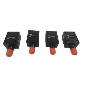
There’s no pilot circuit, no external drain, no feedback stage. The valve responds directly to whatever pressure the system puts on it. That simplicity is actually an advantage for maintenance — fewer things to go wrong, fewer things to inspect. The main failure modes are contamination on the seat, wear on the cone or seat surface, and spring preload loss. That’s pretty much the whole list.
The “315″ in DBDS20K10/315 is the pressure setting — 315 bar. That means the spring is preloaded to resist 315 bar of hydraulic force on the cone face. It sits at that compression continuously, for as long as the system is pressurized. Which leads directly to the relaxation problem.
Spring Relaxation — Why It Happens and Why It Matters
Any spring held under sustained compression will gradually lose some of its load over time. This is stress relaxation — a slow, time-dependent deformation at the grain level of the spring wire, driven by the ongoing stress the compression creates. It’s not a manufacturing defect. It happens to all spring steels. The only variables are how fast it happens and how much preload is lost by a given point in the spring’s service life.
Temperature makes a significant difference here. A spring running in a hydraulic system where fluid temperatures regularly hit 60°C or above will relax considerably faster than one running at 40°C. If the valve is mounted near a heat source — close to a pump, in a poorly ventilated cabinet, or in a part of the turbine hall that runs hot — the relaxation rate goes up. This isn’t something you can see or measure easily during a visual inspection, which is part of what makes it easy to overlook.
The practical result is that the cracking pressure of the DBDS20K10/315 slowly drops below 315 bar. How far it drops depends on operating conditions, but for a valve running within its rated temperature range, drift of 2 to 5 percent over the first 5,000 operating hours is a reasonable expectation. At 315 bar, that’s somewhere between 6 and 16 bar of downward shift.
Whether 6 to 16 bar matters depends entirely on how the valve is being used and what margin exists between normal system operating pressure and the relief valve set point. If the system runs at 280 bar and the relief valve is set at 315, a 10-bar drift still leaves 25 bar of margin — probably fine. If the system runs at 300 bar with a 315 bar relief setting, a 10-bar drift means the valve starts cracking during normal operation. That’s a different situation entirely.
What Happens When the Set Pressure Drifts Into the Operating Range
This is where the real-world consequences show up. A relief valve that’s cracking at or near normal system operating pressure isn’t just failing to protect the system at its rated limit — it’s actively interfering with normal operation.
Every time system pressure approaches the drifted cracking point, the cone lifts slightly and bypasses a portion of flow to the return line. That bypassed flow converts hydraulic energy directly to heat. Oil temperature climbs. In a system without great cooling margin, this can push fluid temperatures into ranges that accelerate oil degradation and further soften the spring — a self-reinforcing problem.
The cone reseating repeatedly under these conditions also wears the seating surfaces. A seat that’s been cycling at low lift thousands of times starts to show contact wear, which then affects sealing quality and can cause the valve to weep at pressures below the cracking point. By the time the maintenance team investigates, the valve has both a set pressure problem and a sealing problem — and sorting out which came first isn’t always straightforward.
Pump loading goes up too, because the pump is now delivering flow that the relief valve is partially bypassing rather than delivering usefully to the actuators or system functions the pump is supposed to serve.
Is the 5,000-Hour Spring Check Actually Realistic?
Technically, yes. Practically, it depends heavily on how the system is set up and what the plant’s maintenance windows look like.
Checking the spring preload on a DBDS20K10/315 isn’t a quick job. The valve needs to be isolated from system pressure. The adjustment cap and locknut need to come off. You need to either measure spring deflection and compare it against spec, or do a functional cracking pressure test using a portable test rig. Then reassemble with correct torque and locking. In a congested turbine hall with this valve buried behind other equipment, access time alone can make this a multi-hour task.
Most power plants don’t have a natural maintenance window at the 5,000-hour mark. A unit running 8,000 hours a year between major outages isn’t going to take a hydraulic system isolation just to check a relief valve spring. It doesn’t fit the operational schedule, and the disruption isn’t worth it unless there’s a specific reason to suspect a problem.
What actually works better in most plants is a functional pressure check during planned outages — using a portable pressure test rig at system test points to verify the actual cracking pressure, without necessarily pulling the valve apart. If the cracking pressure has drifted more than 5% from set point, the valve gets readjusted or replaced. If it’s within tolerance, it goes back into service with a note in the maintenance record.
This approach requires test points to be available in the hydraulic circuit near the relief valve. In older plant designs, those test points often weren’t installed. Adding isolation valves and test connections as part of a planned system upgrade is one of those improvements that seems minor but makes condition-based maintenance genuinely practical rather than theoretical.
Operational Signs That Something May Be Wrong
You don’t always have to wait for a scheduled check to notice a drifted relief valve. A few things in normal plant operation can point in that direction:
- Hydraulic oil temperature running higher than normal with no obvious cause — the relief valve cracking during normal operation is a common but frequently missed source of excess heat
- System pressure that varies more than usual under steady load, or sits slightly lower than the historical baseline
- Valve chatter — an audible or detectable rapid cycling as the cone lifts and reseats near the drifted cracking pressure
- Pump current or power draw trending higher, suggesting flow is being bypassed rather than delivered usefully
- Faster than expected rise in oil contamination, from cone seat wear generating metallic particles
None of these is conclusive on its own. But if two or three show up together — especially in a system where the DBDS20K10/315 hasn’t been verified in a while — it’s worth moving the valve up the inspection list rather than chasing other causes first.
Maintenance Intervals: A Practical Reference
| Trigger | Action | Notes |
|---|---|---|
| Planned outage (or approximately every 8,000 hrs) | Functional cracking pressure test | Portable test rig at circuit test points is the practical approach |
| Unexplained oil temperature rise | Check relief valve cracking pressure early in the investigation | Partial opening during normal operation is a common and overlooked heat source |
| System pressure instability | Inspect cone seat for wear or contamination | Debris on the seat causes erratic cracking behavior |
| Cracking pressure drift confirmed above 5% from set | Readjust or replace | Readjustment viable only if seat condition is still good |
| After a system temperature excursion | Bring forward the next cracking pressure check | High temperatures accelerate spring relaxation significantly |
Readjust or Replace?
When the cracking pressure check shows the DBDS20K10/315 has drifted out of tolerance, the decision between readjusting and replacing comes down to the valve’s service history and the condition of the internal parts.
A valve that’s been in service for a long time, shows visible seat wear, and has already been readjusted before is usually better off being replaced. The spring in a valve with significant hours on it has already relaxed through the steeper early part of its relaxation curve, but it will continue to drift — and a spring that’s been compressed and fatigued over thousands of hours won’t hold a readjusted set point as well as a fresh spring will.
A worn cone or seat that’s been readjusted to compensate for drift may also not seal cleanly at the new pressure setting. Internal leakage at a valve that looks correct from the outside is a problem that’s easy to miss and annoying to diagnose later.
Replacing with a correctly specified DBDS20K10/315 — matched to the system’s actual pressure requirements, not just cross-referenced by physical fit — gives you a known starting condition and a predictable service baseline going forward. If you’re sourcing a replacement or checking whether a cross-reference is genuinely equivalent for your application, a supplier with hydraulic valve experience can verify the specification quickly against your system design pressure and flow data.
The valve itself is not expensive relative to the hydraulic systems it’s protecting. Treating it as a service item on a sensible inspection cycle — rather than a fit-and-forget component — is usually the more cost-effective approach over the long run.
Post time: Jul-06-2026
-

Steam turbine actuator oil filter DL004001
-

SZC-04FG wall mounted rotational speed monitor
-

Vacuum pump rocker seal P-1764-1
-

Boiler reheater inlet isolation valve SD61H-P35...
-

Hydraulic Oil Cycle Pump Suction Filter WU-63&#...
-

G761-3033B DEH system electro-hydraulic servo v...
-

NXQ series EH oil system accumulator Rubber bla...
-

GJCF-15 APH Gap Control system Signal Transmitter
-

LVDT Sensor TDZ-1E-32
-

Filter element QF1D350CJJHC
-

Jacking oil pump discharge filter DQ8302GAFH3.5C
-

Metal gasket HZB253-640-03-24