

The XDH-20C is a capacitor-discharge high-energy igniter designed for boiler burner ignition systems. It converts a 220V AC supply into a 3000V DC charge stored in a capacitor bank, then releases that energy in a controlled pulse through a semiconductor ignition nozzle at the oil gun tip. When the ignition circuit works, the arc is immediate and visible. When it doesn’t, finding the fault quickly is what keeps the boiler lighting window open.
How the Capacitor Discharge Circuit Works
The XDH-20C igniter takes standard 220V power frequency input and steps it up through an internal transformer, then rectifies it to produce approximately 3000V DC. That voltage charges a storage capacitor continuously while the unit is powered. The capacitor doesn’t release its stored energy until the gas discharge tube — a control element sensitive to voltage level — reaches its breakdown threshold and fires.
At the moment of discharge, the energy stored in the capacitor releases almost instantaneously through the discharge tube and travels down the shielded high-voltage cable to the ignition nozzle at the burner. The semiconductor ignition nozzle converts that pulse into a high-energy arc — a sharp, bright blue spark capable of igniting light oil, heavy oil, or low-calorific-value gas fuels directly.
The discharge repeats at a frequency determined by the charging rate and the discharge tube’s firing characteristics — typically producing a series of rapid, consistent sparks rather than a single event. This repetitive firing pattern is important because it gives the fuel several ignition opportunities per second during the lighting window, not just one.
The shielded cable between the igniter unit and the ignition nozzle carries high-voltage pulses. The shielding is both for electrical noise suppression and for personnel safety — the cable must be intact and the insulation undamaged for the pulse to arrive at the nozzle at usable energy levels rather than dissipating along the cable run.
The Ignition Nozzle: The Final Link in the Chain
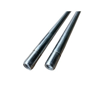
The semiconductor ignition nozzle — the component physically installed in or near the oil gun tip — is where the electrical pulse becomes an arc. Its construction uses a semiconductor gap material that provides a defined breakdown path for the high-voltage pulse. The spark forms across this gap and contacts the fuel-air mixture at the burner mouth.
Nozzle condition is the single most common reason an otherwise functional high-energy igniter fails to produce ignition. Carbon deposits from incomplete combustion, fuel oil contamination of the gap surface, or physical cracking of the semiconductor body all degrade the spark. A nozzle that has been in service for a long time may still produce a spark, but a weaker one — not visually obvious, but not energetic enough to reliably ignite heavy oil or a fuel-rich mixture.
The nozzle is also the easiest component to inspect. Pulling the oil gun out of the burner gives direct access to the nozzle tip. Energising the high-energy igniter with the nozzle visible — and with appropriate safety precautions given the voltage levels involved — shows immediately whether a strong blue arc is forming. That single observation tells you more than any DCS status reading.
DCS Signal Interpretation: What the Control Room Sees
Modern boiler burner systems run ignition sequences through the DCS or BMS (burner management system). The XDH-20C igniter connects to this system through a command input — the DCS sends a run signal to the igniter — and typically returns a feedback status signal indicating whether the igniter has received the command and is powered.
What the DCS cannot directly confirm is whether a spark is actually reaching the burner. The flame detector does that. So when an operator issues an ignition command and the flame detector shows no flame after the expected delay, there are two possible interpretations: the igniter fired but couldn’t ignite the fuel, or the igniter didn’t fire at all. The DCS status alone doesn’t separate these.
A correctly functioning high-energy igniter will show its run feedback signal active as soon as the command is received and power is confirmed. If that feedback is absent when the command is sent, the problem is upstream of the igniter itself — check the control circuit wiring, the supply voltage at the igniter terminals, and any intermediate relay or contactor in the ignition control loop before assuming the igniter unit has failed.
If the run feedback is present but flame detection shows no fire, the igniter is receiving power but the ignition nozzle may not be producing a usable spark. That’s the condition where on-site inspection is faster and more decisive than any further DCS-level diagnosis.

On-Site Fault Diagnosis: The Fastest Path to Restoration
When the control room and field teams are coordinating on a failed ignition, the field check sequence matters. Time pressure during a boiler lighting attempt is real — the fuel admission window has limits, and repeated failed ignition attempts mean the furnace purge cycle resets before another attempt can be made.
Step 1: Check the Igniter Indicator Light
The XDH-20C has a status indicator on the unit body. With the ignition command active, this light should show the unit is powered and running. If the indicator is dark, the unit is not receiving power — verify the supply breaker, control fuse, and incoming supply voltage before anything else. A dark indicator with the DCS command confirmed active points to a wiring or supply issue, not an igniter failure.
Step 2: Listen at the High-Voltage Cable
Stand close to the shielded cable run from the igniter to the burner while the igniter is commanded on. A functioning high-energy igniter produces an audible clicking or crackling sound at the cable as each capacitor discharge pulse travels through. This sound is faint through the cable shielding but detectable if you’re within a metre or so. No sound means the igniter is either not producing pulses or the discharge tube has failed to fire.
Step 3: Inspect the Ignition Nozzle Directly
Pull the oil gun out so the ignition nozzle is accessible and visible. Energise the igniter — with all safety precautions in place — and observe the nozzle gap. A healthy spark is a sharp blue arc, bright enough to see clearly in typical plant lighting conditions. A weak, faint, or absent spark tells you the problem is at the nozzle end of the circuit, not the igniter unit itself.
This is the most direct test available in the field. It takes less than two minutes if the oil gun can be withdrawn quickly, and it immediately tells you whether the fault is in the igniter, the cable, or the nozzle.
Fault Tracing When No Spark Is Present
If the ignition nozzle inspection confirms no arc, work through the circuit in the order that takes the least time to check and has the highest probability of finding the fault:
| Check Sequence | What to Look For | Action If Fault Found |
|---|---|---|
| 1. Connector and terminal contacts | Loose or corroded connections at the cable-to-igniter terminal, the cable-to-nozzle connector, and any intermediate junction box. Oxidised contacts are the most common cause of intermittent spark failure. | Clean contact surfaces, re-seat connectors firmly, and apply contact protection if corrosion is found. Re-test spark before proceeding further. |
| 2. High-voltage shielded cable | Visible damage to cable insulation — cuts, kinks, heat-affected sections near the burner, or areas where the cable has been pinched by equipment. Internal breaks in the conductor or shielding may not be visible externally. | If external damage is visible, replace the cable. For suspected internal faults, a simple continuity check won’t find a high-voltage breakdown — the cable needs to be tested under load or substituted with a known-good section. |
| 3. Ignition nozzle | Carbon fouling or oil contamination at the spark gap; physical cracking of the semiconductor body; erosion of the gap electrodes that has widened the gap beyond the design dimension. | Clean the nozzle gap with a dry cloth or compressed air and re-test. If spark is still absent or weak, replace the nozzle. Do not attempt to adjust the gap mechanically on a semiconductor nozzle. |
| 4. Discharge tube inside the igniter | The gas discharge tube is the control element that triggers capacitor discharge. It has a finite service life and can fail open (no discharge) or fail to reach its triggering threshold consistently. This is an internal igniter component. | If all external checks are clear and no spark is produced, the discharge tube is the remaining suspect. This requires opening the igniter unit — refer to the manufacturer’s service instructions. In most field situations, replacing the complete igniter unit is faster than sourcing and replacing the tube alone. |
The sequence above runs from fastest-to-check to most involved. Contact issues resolve in minutes with a screwdriver and cleaning cloth. Cable replacement takes longer but is straightforward. Nozzle replacement is a standard maintenance action. Discharge tube failure means the igniter unit itself needs attention — and that’s where having a spare unit on-site versus waiting for a repair becomes the difference in lighting timeline.
Common Conditions That Accelerate Nozzle and Cable Degradation
The ignition nozzle sits at the burner mouth — one of the harshest locations in the boiler burner system. Repeated thermal cycling, exposure to unburned fuel during failed ignition attempts, and the mechanical handling involved in oil gun insertion and withdrawal all shorten nozzle life compared to what the design specification assumes in steady-state operation.
Heavy oil service is harder on nozzles than light oil or gas. Residual oil baking onto the spark gap between firing cycles creates a conductive deposit that eventually shorts the gap, producing no spark or a visible arc that travels along the deposit rather than across the designed gap. Regular inspection and cleaning at scheduled intervals — not just when ignition fails — keeps the nozzle working through more operating cycles before replacement is needed.
The shielded cable picks up degradation from heat if it’s routed too close to hot surfaces in the burner area. High-voltage cable insulation rated for the operating environment is not universally interchangeable — substituting a lower-rated cable because it’s the right connector size will result in earlier insulation breakdown under the 3000V pulse load. Check the cable specification before any replacement.
Planned Maintenance for the XDH-20C Circuit
Boiler ignition systems tend to receive attention reactively — when a lighting attempt fails during a start sequence. The components that fail in service are the same ones that respond well to scheduled inspection: the nozzle, the cable condition check, and the connector contacts.
- Inspect and clean the ignition nozzle at each planned boiler outage — or more frequently in heavy oil service where carbon accumulation is faster
- Check cable insulation condition and connector seating at the same interval; look for heat-affected sections near the burner and any signs of chafing along the run
- Verify igniter supply voltage at the unit terminals and confirm the DCS command feedback loop is operating correctly at least once per maintenance cycle
- Keep a minimum of one spare ignition nozzle and one spare shielded cable assembly in site stock — these are the components most likely to require replacement between planned outages
E-mail: sales@yoyik.com
Tel: +86-838-2226655
Whatsapp: +86-13618105229
Yoyik offers various types of power plants spare parts for steam turbines, generators, boilers as below:
ROTATE SPEED PROBE ZS-02 L=90
Jingjiang juli valve 150
tool for heating up bolts 2J-14-2R
Displacement transmitter WY-01
Bolt electric heating rod ZJ-20-48
BENTLY Cable 330704-000-060-10-02-00
capacitor CBB24S
eddy current transducer CON021/916-200
Wear-resistant thermal resistor WNKBX-200NK
vibration and strain measurement HD-ST-A3-B3
Security Controller KR-939B3
LIMIT SWITCH C62D
Air Pressure Regulator 67CFR-225/SB
mahindra bolero pickup sensor ZS-04-75-3000
bolts heater 1.2311(4)-φ27.5X800
Eddy Current Sensor PR6424/001-140
Shaft Vibration Probe TM0180-A07-B00-C06-D50
Auxiliary switch for circuit breaker NQ22H123300
MOTOR MANAGEMENT RELAY WDZ-5232A-521130-D220178
Thyristor NFP-KC5
Post time: Jun-02-2026
-

Stainless Steel Bellows Globe Valve WJ40F-1.6P
-

Accumulator air inlet valve QXF-5
-

LVDT sensor 1000TD
-

KR-939SB3 Integrated Three-Parameter Combinatio...
-

23D-63B steam turbine turning solenoid valve
-

Regeneration oil pump suction filter HQ25.300.12Z
-

EH oil main pump discharge filter DP1A601EA01V/-F
-

LVDT sensor TDZ-1-50
-

Generator Stator Cooling Water Filter MSL-125
-

Boiler anti-blocking air pressure sampler PFP-B-II
-

Recycle pump washing oil filter DP1A401EA01V/-F
-

Needle Valve DN40 PN35