

The ME5.530.172 is the local display and control module fitted to motor-operated valve (MOV) electric actuators. It gives operators direct access to valve position feedback, operating parameters, and fault status at the actuator itself — independent of what the DCS is showing in the control room. When the screen goes dark, the diagnostic path that gets the actuator back in full service fastest is a systematic voltage measurement sequence, not a component swap.
What the Display Card Does in an Electric Actuator
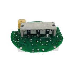
Electric actuators on MOVs contain multiple internal modules: the power board that drives the motor, the logic board that handles control commands and position feedback, and the display card that presents all of this to anyone standing at the valve. The ME5.530.172 handles that last function — it receives data from the main control board and renders it on the local LED or LCD display, and it processes local keypad inputs for configuration, parameter setting, and manual operation.
For commissioning and maintenance, the display card is where most of the work happens. Setting torque limits, configuring travel limits, reviewing fault logs, and verifying valve position readings — all of that goes through this interface. Without it, the actuator may still function on remote commands, but the local operator has no visibility into what the actuator is doing or why.
The display card receives its operating power from the actuator’s internal power supply, which in turn draws from the main supply — typically 220V DC or 110V DC depending on the site installation. Internally, the display card’s power conversion module steps that down to the low voltages the electronics actually need: commonly 5V for logic circuits and 12V for display elements. Both conversions need to be working for the screen to show anything.
The Black Screen: What It Usually Is Not
A dark screen on the ME5.530.172 gets attributed to a failed LED panel or a bad display component more often than it should be. That assumption leads to unnecessary card replacement — only to find the replacement also shows a dark screen once installed, because the actual problem was in the supply chain feeding the display card, not the card itself.
The more informative starting observation is this: if the actuator responds normally to remote open/close commands from the DCS while the local display is dark, the main control board and motor drive circuits are receiving power and functioning. The display card is not getting what it needs, but something else in the actuator is. That narrows the fault significantly before a multimeter is even picked up.
Three distinct fault locations can produce a black screen on the ME5.530.172:
- The external supply circuit — wiring, fuses, or the incoming DC supply to the actuator enclosure
- The internal connection between the actuator’s power board and the display card — a connector, harness, or the power board output itself
- The display card’s own internal power conversion module or MCU drive circuitry
The voltage measurement sequence described below works through these three in the order that takes the least time to rule out.
Voltage Measurement: The Fastest Diagnostic Path
A digital multimeter is the only tool needed for the initial fault isolation. Set it to DC voltage and work through the following checkpoints in sequence. Stop when you find the measurement that doesn’t match expected values — that’s where the fault boundary is.
Measure the Input Supply at the Display Card Connector
The display card has an input connector that receives the main supply from the actuator’s power board — 220V DC or 110V DC depending on the installation. With the actuator energised, measure the voltage at the display card input terminals directly. Don’t measure at the supply panel and assume it’s reaching the card; measure at the card.
If the voltage is absent or significantly below nominal, the fault is upstream of the display card. Check the wiring harness from the power board to the display card connector, the connector itself for oxidation or a loose pin, and any inline protection components — fuses or polarity protection diodes — between the power board and the card. A missing voltage here has nothing to do with the display card’s internal circuitry.
If the input voltage is correct — 220V DC where 220V is expected, within a reasonable tolerance — the supply is reaching the card. The fault is inside the display card.
Measure the Internal Low-Voltage Rails
With the input voltage confirmed present, the next measurement is the output of the display card’s internal DC-DC converter. These are the low-voltage rails that feed the MCU and display elements. On most display card designs in this class, the test points or output pins for these rails are accessible with the card in situ — typically marked on the PCB or identifiable from the component layout around the converter IC.
Measure the 5V rail and the 12V rail (or whichever low-voltage outputs this specific card design uses — refer to the service documentation for ME5.530.172 for the exact values). If either rail is absent or out of specification, the DC-DC converter module has failed. The input voltage arrived; the conversion didn’t happen.
A failed DC-DC converter on a display card is a component-level fault. In most field maintenance situations, the practical response is to replace the ME5.530.172 display card as a unit. Component-level repair of the converter module is possible but requires PCB rework capability and the correct replacement part — not feasible in a power plant maintenance bay during an outage.
Low-Voltage Rails Present But Screen Still Dark
If both the input supply and the low-voltage rails are confirmed within specification but the display remains dark, the fault has moved downstream of the power conversion. At this point, the MCU or its display driver circuit is the remaining candidate — it’s receiving power but not producing output to the display panel.
This is less common than a supply or converter fault, but it does occur — particularly in actuators that have experienced a voltage transient or a supply polarity reversal at some point. The MCU failure mode often presents as a completely dark screen with no response to keypad input, whereas a power conversion fault typically produces a dark screen with no keypad response either but for a different reason.
Distinguishing a converter fault from an MCU fault matters mostly for repair decisions. Both ultimately require card replacement under field conditions.
Voltage Fault Isolation: Summary Reference
| Measurement Point | Expected Reading | Fault Indicated if Abnormal |
|---|---|---|
| Input supply at display card connector | 220V DC (or 110V DC per site spec), within ±10% | Upstream fault — check wiring harness, connectors, inline fuses, and power board output. Display card is not the fault. |
| 5V logic rail at DC-DC converter output | 4.75V – 5.25V DC | DC-DC converter module has failed. Input present but conversion failed. Replace display card. |
| 12V display rail at DC-DC converter output | 11.4V – 12.6V DC | DC-DC converter module has failed (12V output). Same action as above. |
| All rails present; display dark; no keypad response | N/A — power is reaching MCU | MCU or display driver circuit fault. Likely caused by voltage transient or component failure. Replace display card. |
| All rails present; display dark; keypad responds | N/A — MCU functioning | Display panel or display driver output fault. Card replacement or display element replacement depending on card design. |
Remote Operation During a Local Display Fault
The ME5.530.172 display card failure — in any of its forms — does not interrupt remote control of the actuator through the DCS. The main control board continues to receive and execute open/close commands, and position feedback signals continue to be transmitted to the control room. From a process perspective, the valve remains operable.
What is lost is the local operator interface. No local position readout, no local keypad control, and no access to fault log data or parameter settings until the display card is restored. For routine operation during a planned outage, this may be acceptable. For commissioning, limit setting, or troubleshooting another fault on the same actuator, it is not — the display card needs to be working.
Document the remote operability status clearly in the fault record. It affects whether the repair is treated as an emergency (the valve cannot be operated at all) or a scheduled maintenance item (the valve operates on remote commands, and local display restoration is planned for the next available window).
Preventing Repeat Failures
Display card failures on electric actuators in power plant environments tend to cluster around a few identifiable causes. Addressing them after the first failure reduces the likelihood of a second.
- DC supply quality: High-voltage DC supplies in substations and auxiliary systems carry transient spikes from switching events. The display card’s power conversion module is the first component to see those transients. Check whether surge protection is installed on the DC supply feed to the actuator enclosure — if not, it’s worth adding for any actuator on a critical valve.
- Connector condition: The plug-in connector between the actuator power board and the display card is exposed to the same vibration and thermal cycling as the rest of the actuator. Periodic reseating of the connector during scheduled maintenance — and application of contact protection to prevent oxidation — is a simple preventive step that avoids a common cause of supply interruption to the card.
- Enclosure sealing: Moisture ingress into the actuator enclosure accelerates PCB corrosion on the display card and degrades connector reliability. Check enclosure seals and cable entry glands at each maintenance visit, particularly on actuators installed in exposed outdoor locations or near steam vents.
Keeping one spare ME5.530.172 display card on site for each critical valve type reduces restoration time when a card fails during operation. The voltage measurement sequence described above takes a few minutes; having the replacement card available on the same day avoids the lead time that determines how long the local interface stays dark.
E-mail: sales@yoyik.com
Tel: +86-838-2226655
Whatsapp: +86-13618105229
Yoyik offers various types of power plants spare parts for steam turbines, generators, boilers as below:
Eccentric preamplifier 204-450-000-002-A1-B23-H10-I1
eddy current sensors are used CWY-DO-812507
LVDT Sensor 2000TD-10-01-01
Vibration sensor along-with transmitter CWY-D0-01-01
pneumatic pressure regulator AW30-02-D
toxic gas alarm controller MDL-2104-NH3
Travel switch NI4-M12-AD4X
industrial pressure transmitter ST307-350-B
magnetic tachometer working principle G-065-05-01
Thermometer WSS 581W Dial 150mm
THREE PARAMETER SAFETY MONITOR TS-V-73
Displacement Sensors HTD-300-5
Eddy Current Sensor PR6424/011-141
Shaft vibration preamplifier IQS450 204-450-000-002-A1-B21-H05-I0
Water level gauge mica components B68H-32/2-W
Large bolt electric heater ZJ-20-813
Smoke fan speed sensor D-080-02-01
LVDT Sensor TD-1-500-30-01
LVDT TDZ-IE-32
intelligence Hand Operator NPDF-Q20FD0
Displacement transmitter B151.36.09.04.13
Post time: Jun-03-2026
-

Magnetic Liquid Level Indicator UHC-DB
-

Actuator EH oil filter DP401EA03V/-W
-

MM2XP 2-pole 24VDC Digital Power Intermediate R...
-

Double barrel oil filter disc SPL-32
-

Generator Hydrogen sealing Sealant D25-75
-

Generator RTV epoxy adhesive J0792
-

Platinum Resistor Temperature Sensor WZPM-201
-

Jacking Oil Pump Suction Oil Filter DQ6803GA20H...
-

Dual color water level gauge Tempered glass acc...
-

OF3-08-3RV-10 EH oil main tank circulating pump...
-

Regeneration device diatomite filter DL003001
-

Hydraulic oil system filter element FAX 250*10