

Installing an eddy current sensor for steam turbine differential expansion measurement isn’t complicated, but there’s one step that determines whether the sensor actually works correctly — setting the gap between the sensor tip and the target surface so the output voltage falls within the linear range. Get this wrong and the measurement is distorted. The TSI system may still show a number, and that number may even look plausible, but it won’t accurately represent what the turbine is doing.
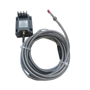
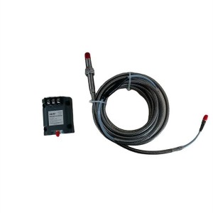
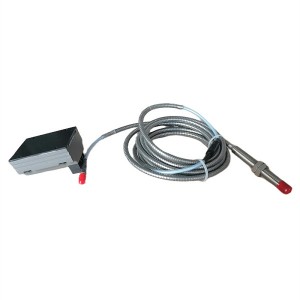
The WT0122-A50-B00-C01 is an eddy current sensor used in steam turbine differential expansion monitoring — measuring the relative axial displacement between the turbine rotor and the casing as the machine heats up and cools down. The gap voltage setup for this sensor is the critical installation step, and it’s worth understanding why before working through the practical procedure.
Why the Gap Voltage Determines Measurement Quality
Eddy current sensors work by generating a high-frequency magnetic field at the sensor tip. When a conductive target surface is close enough to enter that field, eddy currents are induced in the target material, and the resulting impedance change in the sensor coil produces a voltage change at the output. The output voltage varies with gap distance — closer target, lower output voltage; further target, higher output voltage.
The relationship between gap distance and output voltage is only linear across a defined range. Outside that range, at very small gaps and very large gaps, the sensitivity changes — the voltage shift per millimeter of movement isn’t consistent anymore. If the sensor is operating in the nonlinear region, a given amount of actual rotor-to-casing displacement produces a different output voltage change than the same displacement would produce in the linear region. The measurement is no longer trustworthy.
The installation gap voltage is essentially the quiescent operating point — the output voltage when the rotor is in its reference position, with no differential expansion occurring. Setting this voltage correctly places the operating point in the middle of the linear range, leaving headroom in both directions for the rotor to move during startup and operation without the sensor tip drifting into a nonlinear zone.
Recommended Gap and Corresponding Output Voltage for the WT0122-A50-B00-C01
For the WT0122-A50-B00-C01, the typical recommended installation gap is in the range of 1.0 to 1.5 mm, with the corresponding output voltage from the signal conditioning module (proximeter) falling in the region of -10V to -12V DC for a standard ±24V supply configuration. The exact target voltage should be confirmed against the sensor and proximeter datasheet for the specific system integration, because the output voltage at a given gap depends on both the sensor characteristics and the proximeter gain setting.
The linear measurement range for this class of eddy current sensor typically spans approximately 2 mm total — meaning the sensor can track target movement of roughly ±1 mm from the installation setpoint while remaining in the linear zone. For steam turbine differential expansion applications, where the measurement range might be ±5 mm or more depending on the machine, the sensor tip position and the initial gap setting together determine which portion of the full differential expansion range the sensor can accurately cover.
This is why the installation gap matters not just for linearity but for range coverage. A gap set too small means the sensor reaches the lower end of its linear range before the rotor has moved very far in one direction. A gap set too large limits coverage in the other direction. The correct gap centers the operating point so the full expected displacement range falls within the linear zone.
How to Measure and Set the Gap Accurately in the Field
The gap setting procedure is straightforward in principle but requires care in execution. The goal is to position the sensor tip at the correct distance from the target surface while the turbine is at rest, confirm the output voltage matches the target value, and then lock the sensor in place so it stays there.
What You Need
- A calibrated digital voltmeter — the gap is set by measuring output voltage, not by measuring the physical distance directly
- The proximeter (signal conditioner) powered up and connected to the sensor
- The sensor mounting hardware — typically a threaded boss in the bearing housing or casing, with a lock nut arrangement
- A non-magnetic feeler gauge or dial indicator for initial position reference if needed
The Setting Procedure
With the turbine shaft stationary at its reference axial position, thread the sensor into the mounting boss and advance it slowly toward the target surface. Monitor the output voltage at the proximeter output terminals or at the TSI monitor input as you go. The voltage will change as the gap closes — for a negative-output system, it becomes more negative as the sensor approaches the target.
Stop advancing the sensor when the output voltage reaches the target value specified for this installation — typically in the -10V to -12V range as noted above. At this point, the gap between the sensor tip and the target surface corresponds to the recommended installation distance. Hold the sensor body stationary and tighten the lock nut against the mounting boss to fix the position.
After tightening, recheck the output voltage. Lock nut tightening can transmit a small rotational force to the sensor body that shifts the gap slightly. If the voltage has moved outside the acceptable range, loosen the lock nut, readjust, and retighten. It often takes two or three iterations to get the final locked position within the target voltage range.
Record the as-installed output voltage in the maintenance record. This becomes the reference for future inspections — if the gap shifts over time due to vibration or thermal cycling, the voltage change will tell you which direction and by how much.
What Happens When the Gap Is Outside the Linear Range
This is where the practical consequences become concrete. A gap that’s significantly off in either direction produces a sensor that’s operating in a region where the sensitivity isn’t consistent, and the effects show up in the differential expansion measurement in specific ways.
Gap Too Small — Sensor Too Close to Target
When the sensor is too close to the target surface, the output voltage is already at or near the lower end of the sensor’s output range at the reference position. When the rotor moves in the direction that would close the gap further — during positive differential expansion — the sensor output hits its floor quickly and then saturates. The differential expansion signal flattens out and stops tracking actual rotor movement. The TSI system sees a signal that stops changing when it should still be changing.
The practical result: differential expansion is underreported during the phase of turbine startup when the expansion is most rapid. High differential expansion alarm setpoints may not trigger when actual expansion warrants them. This is the “protection refusal to act” failure mode — the protection system doesn’t respond because the input it’s receiving has been artificially clipped.
Gap Too Large — Sensor Too Far From Target
When the gap is too large, the operating point is near the upper end of the linear range. Rotor movement in the direction that increases the gap moves the sensor quickly into the nonlinear region. In the nonlinear zone, sensitivity drops — the same millimeter of actual movement produces a smaller voltage change than it should. Differential expansion is again underreported, now in the negative direction.
But the behavior isn’t always a simple underreporting. In the nonlinear transition zone, the local sensitivity varies in a way that can produce non-monotonic output — the voltage may actually move in the wrong direction briefly as the gap crosses the nonlinear boundary. In a TSI system this can produce brief erroneous readings or a signal excursion that looks like a real expansion event, potentially triggering a spurious alarm.
Gap Setting Outcomes at a Glance
| Gap Condition | Output Voltage at Rest | Effect on Measurement | Protection Risk |
|---|---|---|---|
| Correct gap | Within target range (e.g., -10V to -12V) | Linear tracking across full expected displacement range | None — system functions as designed |
| Gap too small | More negative than target (e.g., -14V or lower) | Signal saturates early; positive expansion underreported | High differential expansion alarm may not trigger |
| Gap too large | Less negative than target (e.g., -6V or higher) | Sensitivity reduced; possible nonlinear excursions | Spurious alarms or underreported negative expansion |
Keeping the Gap Stable Over Time
Setting the gap correctly at installation is one part of the problem. Keeping it there is the other. Steam turbine bearing housings and casings are warm, vibrating structures, and the sensor mounting hardware is subject to the same thermal cycling and mechanical loading as everything else in the area.
Lock nuts are the standard means of securing the sensor position, but a lock nut that’s been in service for years in a hot, vibrating environment can gradually work loose. Checking the output voltage at each planned outage — comparing it against the recorded installation value — confirms whether the gap has shifted without requiring direct access to the sensor tip itself. A voltage that’s drifted from the installed reference value means the gap has changed and the sensor needs to be readjusted.
Some installations add a secondary locking mechanism — a thread-locking compound on the sensor threads, or a set screw in the mounting boss — to reduce the risk of vibration-induced loosening. The appropriate method depends on whether the sensor needs to be removable for maintenance and what the local installation geometry allows.
If you’re commissioning a new differential expansion measurement system using the WT0122-A50-B00-C01 or replacing an existing eddy current sensor on a running turbine, confirming the proximeter gain setting and the target gap voltage range against the system documentation before starting the installation saves time and avoids having to redo the gap setting after discovering a calibration mismatch. Contact your instrumentation supplier if the installation documentation doesn’t include specific gap voltage targets for your configuration.
Summary
The gap voltage setup for the WT0122-A50-B00-C01 eddy current sensor is the installation step that determines whether the differential expansion measurement is accurate across the turbine’s full operating range. The recommended installation gap produces an output voltage in the linear region of the sensor characteristic — typically around -10V to -12V for standard configurations. Operating outside the linear range distorts the measurement in ways that can either suppress alarms that should fire or generate readings that don’t reflect actual rotor movement.
Field setting is done by monitoring the proximeter output voltage while adjusting sensor position, locking the sensor at the correct voltage, and recording the as-installed value as a maintenance reference. Periodic voltage checks at planned outages confirm the gap hasn’t shifted. For differential expansion protection on a steam turbine, this is one measurement that’s worth getting exactly right.
Post time: Jul-15-2026
-

Stator Cooling Water Pump YCZ50-250C
-

Sealing Ring of Generator Hydrogen Cooling System
-

Pressure oil-return filter HQ25.600.15Z
-

AST solenoid valve SV13-12V-0-0-00
-

Stainless Steel Hydraulic Oil Filter 0850R020BN3HC
-

LVDT sensor 1000TD
-

Sealing ring DG600-240-07-03
-

LVDT Position Sensor ZDET-200B
-

Surface cover epoxy air-dry varnish 1504
-

LX-FF14020041XR Compressor air filter element
-

Gas turbine actuator oil filter CB13299-001V
-

Duplex oil filter element LX-FM1623H3XR