

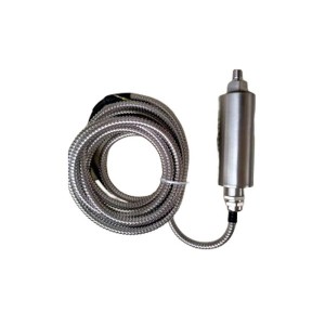
The SZ-6A is an inertial magneto-electric velocity sensor used to measure absolute bearing housing vibration on steam turbines, feed pumps, induced draft fans, and similar rotating machinery. No external power supply is required — the sensor generates its own output voltage through electromagnetic induction as the housing moves. When the DCS starts showing rising vibration values on a channel driven by this sensor, the immediate question is whether the machine is actually deteriorating or whether the sensor or its cable circuit is responsible for what the system is seeing.
How the SZ-6A Generates Its Signal
Inside the SZ-6A, a permanent magnet is suspended on a spring system within the sensor housing. When the bearing housing vibrates, the housing moves with the machine. The magnet, due to its inertia, tends to stay stationary in space. The relative motion between the moving coil — fixed to the housing — and the stationary magnet induces a voltage in the coil proportional to the velocity of that relative motion.
This is absolute vibration measurement: the sensor measures how fast the bearing housing is moving relative to inertial space, not relative to the shaft. That distinction matters for how the data is interpreted. Absolute bearing housing vibration (sometimes called pedestal vibration or seismic vibration) captures the overall vibratory energy transmitted from the rotor through the bearing and into the structure.
Because the output voltage is directly proportional to vibration velocity, the SZ-6A produces a signal that integrates naturally with velocity-based alarm thresholds — the ISO 10816 standard family, for instance, specifies bearing housing vibration limits in mm/s RMS. The DCS reads the SZ-6A signal, converts it to engineering units, and compares it against configured alarm and trip thresholds continuously.
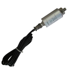
No preamplifier, signal conditioner, or external power supply is needed at the sensor itself. The coil output connects directly to the measurement input through a shielded cable. Simplicity is one of the reasons this sensor type remains common in power plant rotating machinery monitoring despite the availability of more complex alternatives.
What a Rising Vibration Alarm Actually Represents
A DCS vibration value that rises gradually toward the alarm threshold over days or weeks is a different situation from one that jumps to an abnormal level within minutes or hours. Both produce the same alarm, but the underlying cause is usually different — and treating them the same way wastes time.
Gradual increases, particularly those that correlate with changes in load, bearing temperature, or process conditions, tend to reflect actual machine behaviour. The bearing or rotor is changing in a way that produces more vibration. That deserves investigation but follows the pattern of normal condition monitoring response.
Sudden changes — a value that was stable yesterday and is now 40% higher with no change in operating conditions — are more likely to involve the measurement chain rather than the machine. Bearings and rotors change gradually under normal deterioration. They can change suddenly under impact or catastrophic failure, but those events come with other symptoms: temperature rise, noise, power draw changes, or process upsets. A vibration channel that rises sharply in isolation, with everything else stable, deserves scrutiny before the machine is pulled for inspection.
Distinguishing Real Machine Deterioration from Sensor or Cable Faults
The diagnostic approach depends on what data is available and what access is practical during normal operation. Two methods cover most situations without requiring any downtime.
Comparing Adjacent Measurement Points
Most large rotating machines in power plants have vibration sensors on multiple bearing housings — sometimes on both ends of the same machine, or on the driven and driving ends of a coupled train. The SZ-6A is typically one of several sensors on a given piece of equipment.
If a single vibration channel rises while all adjacent channels on the same machine remain stable, the probability of a measurement chain fault on that channel is substantially higher than the probability of a genuine machine fault that affects only one bearing while leaving all others unchanged. True machine deterioration — rotor imbalance, misalignment, bearing damage — typically produces a vibration signature that shows up across multiple measurement points, even if the amplitude differs between them.
A single-channel anomaly, especially an abrupt one, warrants cable and connector inspection before any mechanical conclusion is drawn. Check the sensor cable for damage, check the terminal connections at both ends for looseness or corrosion, and verify the DCS input channel is reading correctly by checking the raw signal against a reference.
Portable Vibration Instrument Cross-Check
A handheld vibration meter placed on the same bearing housing as the suspect SZ-6A provides an independent measurement at the same physical location. This cross-check takes a few minutes and produces a direct comparison between what the installed sensor is sending to the DCS and what a separate, known-good instrument measures at the same point.
If the portable instrument reads a similar value to the DCS — both elevated — the machine is vibrating at that level and the installed sensor is reporting correctly. The machine needs attention.
If the portable instrument reads significantly lower than the DCS is showing, the installed vibration sensor or its signal chain is adding something that isn’t coming from the machine. That points to the sensor, the cable, or the DCS input channel as the fault source — not the bearing.
The reverse situation also occurs: the DCS showing a normal value while the portable instrument measures elevated vibration. This suggests the installed sensor may be attenuated — a loose mounting, a degraded coil, or a high-resistance fault in the cable that’s reducing the signal reaching the DCS. A sensor that reads low is arguably more dangerous than one that reads high, because it creates false confidence about machine condition.
Sensor and Cable Faults: What They Look Like and Why They Happen
The SZ-6A is a passive, moving-coil sensor — mechanically simple, but not immune to failure. The most common fault modes that produce erroneous readings are:
- Coil or spring fatigue: The internal spring suspension that allows the magnet to remain inertially stationary develops fatigue over years of continuous vibration exposure. As the spring characteristics change, the sensor’s frequency response shifts, and readings at certain frequencies become inaccurate.
- Loose or damaged mounting: The SZ-6A must be rigidly coupled to the bearing housing to measure its motion accurately. A loose mounting stud or a gap between the sensor base and the housing introduces mechanical compliance that attenuates the signal. In some cases, a partially loose sensor can rattle at its own resonant frequency and produce a reading that’s higher than actual.
- Cable connector corrosion or damage: The coaxial or shielded cable connecting the sensor to the DCS carries a low-level analogue voltage signal. Corrosion at either connector end increases contact resistance and reduces the signal level. Intermittent contact — from a cable that has been bent repeatedly or damaged at a routing point — produces intermittent signal anomalies that show as spiking values on the DCS trend.
- Shield grounding faults: If the cable shield is grounded at both ends rather than at one end only, ground loops can inject 50 Hz interference into the signal. This appears as a fixed elevation in the vibration reading unrelated to actual machine vibration, and it’s particularly misleading because it’s constant and stable — it looks like a real steady-state vibration level.
Alarm Pattern Reference: Machine vs Measurement Chain
| Alarm Characteristic | Suggests Machine Fault | Suggests Sensor or Cable Fault |
|---|---|---|
| Rate of change | Gradual increase over days or weeks, tracking load or temperature changes | Sudden step change without any process event; or stable reading that jumps to a fixed elevated value |
| Number of channels affected | Multiple bearing positions on the same machine show increases simultaneously | Single channel anomaly while all adjacent channels remain stable |
| Portable instrument comparison | Portable meter agrees with DCS reading at the same bearing housing | Portable meter reads significantly different from DCS on the same housing |
| Correlation with other parameters | Bearing temperature rising alongside vibration; process changes precede vibration change | No correlated changes in temperature, load, or process; anomaly appears in isolation |
| Timing of onset | Develops during normal operation with gradual progression | Onset immediately after maintenance work in the area; or after a cable disturbance event |
Sensor Mounting and Cable Practices That Protect Signal Quality
The SZ-6A is calibrated as a complete sensor-cable assembly in some configurations and as a sensor alone in others. In either case, the physical installation determines how well the sensor performs over its service life.
Mounting rigidity matters as much as sensor condition. The mounting surface on the bearing housing should be flat, clean, and free of paint or scale in the contact area. A stud-mounted sensor must be tightened to the specified torque — under-tightened, and the sensor can shift under vibration; over-tightened on a cast housing, and the stud pulls out or the housing thread strips.
Cable routing from the sensor to the nearest junction box should avoid contact with hot surfaces and sharp edges. The cable needs strain relief at the sensor connection point — vibration transmitted through a cable that is rigidly fixed immediately at the sensor connector will eventually fatigue the internal conductors at that point. A short loop of slack at the sensor end absorbs the vibration without stressing the connection.
Condition-Based Maintenance and the SZ-6A
The SZ-6A is positioned in condition-based maintenance programmes as the primary data source for bearing health assessment. Its signal feeds the DCS trend records and alarm functions that determine when maintenance is needed. That role only works if the sensor’s own condition is periodically verified.
A sensor that has been in service for several years on a high-vibration machine should be checked during any planned outage that provides access to the bearing area. The check doesn’t require specialist equipment — a portable vibration meter placed next to the installed sensor while the machine is running gives an immediate read on whether the DCS values match field reality.
When a sensor replacement is warranted, record the baseline reading with the new sensor at the next normal operating condition. That first post-installation reading becomes the new reference point for that measurement position, and any deviation from it in subsequent monitoring is measured against a known baseline rather than against a historical trend that may reflect both machine changes and sensor degradation accumulated over years.
E-mail: sales@yoyik.com
Tel: +86-838-2226655
Whatsapp: +86-13618105229
Yoyik offers various types of power plants spare parts for steam turbines, generators, boilers as below:
Monitoring instrument DYX-R
Eddy Current Sensor PR6424/004-100
6KV TRANSFORMER PROTECTION RELAY NEP 983
Direct-current heating controller DJZ-03
speed meter DF9011-B
transducer for measurement of displacement DET-50B
Rectifier bridge cooling fan GDRM42
low cost lvdt TD-1 100S
Eddy Current Signal Converter CON011
Oil-water separator FMH-2R
CONVERTER GD2133007
Pressure vacuum gauge (-0.1-0MPa)Diameter:150mm,Accuracy: 1.6/2.5 YZ-150
boiler pressure indicator 3051GP2A2B21BB4M5HR5
high temperature pressure transmitter MIX7B62B59
Temperature switch T768TS040XCNC4 20/95C
differential pressure indicator switch 3051CD1A2B21AM5B4Q4
Overspeed protection DN3.6C.OPC.000A
Pressure Switch 02-139488
Displacement Sensors 10000TDKGN-DL-HTC
LVDT MSV TD-1-250
Post time: Jun-04-2026
-

Steam Turbine Shutoff valve F3RG03D330
-

Jacking Oil Pump Suction Oil Filter DQ6803GA20H...
-

Coal Feeder Load Cell AC19387-1
-

EH oil main pump skeleton oil seal TCM589332
-

Epoxy-ester air-drying red insulating varnish 9130
-

Intelligent Reversal Speed Monitor JM-D-5KF
-

HL Series Displacement Sensors
-

DFSS type steam turbine cylinder sealing grease
-

EH oil circulating pump oil filter element HC89...
-

Dry-type Transformer Cooling Fan GFD590/126-710
-

Linear variable displacement transducer LVDT se...
-

Solenoid Valve DF-2005