

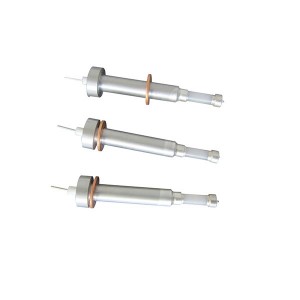
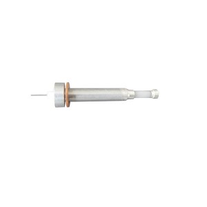
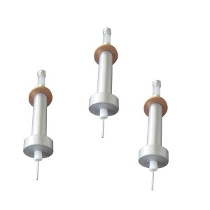
The DJM1615-87 is an external-thread electrode rod for electric contact water level gauges installed on boiler drums, high and low pressure heaters, and deaerators. It forms the core sensing element of the level measurement chain — the component that determines, at each discrete measurement point, whether water or steam is present. When the secondary instrument starts showing erratic signals at a particular point, knowing whether the problem is the electrode rod itself or the instrument channel behind it is the difference between a quick field fix and an unnecessary shutdown.
Construction and Why It Handles Boiler Conditions
The DJM1615-87 electrode rod combines 99.9% high-purity alumina ceramic with alloy steel, sealed together through a ceramic-to-metal brazing process. The ceramic body provides electrical insulation between the electrode tip and the measurement chamber wall, while the alloy steel provides the mechanical structure and the threaded connection to the gauge body.
That brazing joint is critical. It has to stay gas-tight at elevated temperature and pressure simultaneously — conditions that would cause conventional adhesive or mechanical seals to fail. The ceramic-to-metal bond in this construction is rated for the pressure and temperature ranges of medium and high-pressure boilers, which is why it appears in drum water level gauges rather than simpler industrial level switches.
The operating principle is straightforward. Water conducts electricity; steam does not. When the water level rises above an electrode tip, the circuit completes through the conductive water between that electrode and the reference electrode. When steam replaces water at that position, the circuit opens. The secondary instrument reads this as a change in contact state and updates the level display accordingly.
The resistance at the water-steam interface is not a fixed value. It changes with water conductivity, temperature, and the presence of dissolved solids or treatment chemicals — all of which vary with boiler load and water treatment practice. That variability is important context for understanding why some apparent faults at the interface position are not electrode failures at all.
What Causes Signal Flicker and Status Reversals on the Secondary Instrument
An indication light that flickers or toggles between states at a single electrode position, or one that shows the opposite status from adjacent electrodes in a way that doesn’t match the expected water level logic, gets reported as an electrode failure far more often than it actually is one.
Two non-failure causes account for most of these presentations.
Scale Deposit on the Electrode Surface
In hard water or poorly treated boiler water, dissolved calcium and magnesium compounds deposit on the electrode tip over time. The scale layer is semiconducting rather than fully insulating — it has a measurable but unstable resistance. When the electrode tip is at or near the water-steam interface, that scale creates a fluctuating partial contact that reads alternately as water-covered and steam-covered as the water level oscillates slightly around the electrode position.
The secondary instrument interprets this unstable resistance as a flickering contact. The electrode tip is not damaged; it’s dirty. The indication behaviour disappears if the measurement chamber is blown down or if the electrode is cleaned.
Steam-Water Mixture at the Interface Electrode
The electrode position exactly at the water surface experiences the most variable conditions. During load changes, pressure fluctuations, or when the drum steam-water separation is disturbed, the local fluid at that position transitions rapidly between water and steam. The level gauge electrode registers each transition. If the transitions are fast enough, the secondary instrument sees a rapid alternation of contact states — which looks like a faulty electrode but reflects normal hydraulic variability at the measurement point.
This is particularly common after boiler load swings or during blowdown operations. It’s also more pronounced on electrode positions near the alarm setpoints, where any small level variation crosses the contact threshold repeatedly.
Testing Without Stopping the Boiler: The Short-Circuit Method
The most direct on-load test for a suspect level gauge electrode is a controlled short-circuit of the signal input to the secondary instrument. This bypasses the electrode and the measurement chamber entirely and forces the secondary instrument’s input channel into a known state.
With the secondary instrument isolated and the relevant electrode signal cable accessible at the instrument terminal strip, short the electrode signal input terminal to the reference potential terminal — the same reference that the measurement circuit uses when water bridges the electrode to the reference electrode. This simulates the “water present” condition at that electrode position by creating a low-resistance path through the wiring rather than through actual conductive water.
If the corresponding indication light changes to its “water present” state when the short is applied, the secondary instrument channel is functioning correctly. The fault is in the electrode, the measurement chamber, or the signal wiring between the gauge body and the instrument. If the indication light does not respond to the short-circuit, the secondary instrument’s input channel for that point is not working — replacing the electrode rod will not fix it.
This test takes a few minutes at the instrument panel and requires no access to the pressurised measurement chamber. It definitively separates electrode-side faults from instrument-side faults before any mechanical work begins on the gauge body.
Signal Simulation for Deeper Fault Isolation
Where the short-circuit test confirms the instrument channel is suspect, signal simulation provides the next level of detail. The goal is to determine whether the channel input circuit is the fault or whether the fault is further downstream in the instrument’s processing and display circuits.
Simulating the Full Resistance Range
The DJM1615-87 level gauge electrode produces a signal that the secondary instrument sees as a resistance value — low resistance when water bridges the circuit, high resistance (open circuit) when steam is present. A variable resistor or a decade resistance box connected at the instrument input terminals allows the technician to step through the full range of resistance values and observe where the instrument’s response changes.
At low resistance (simulating water), the instrument should indicate “water present.” At high resistance or open circuit (simulating steam), it should indicate “steam” or “dry.” If the transition between these states happens at the expected resistance threshold, the channel is reading correctly. If the channel shows no response across the full resistance range, the input circuit is damaged.
Comparing Adjacent Channels
Most electric contact water level gauges have multiple electrode positions on the same secondary instrument. If one channel is suspect, running the same short-circuit and simulation tests on an adjacent functioning channel and then repeating on the suspect channel confirms whether the fault is specific to one channel module or systemic to the instrument’s power supply or common reference circuit.
A fault that appears only on one specific channel input, with other channels functioning normally under the same test conditions, isolates the fault to that channel’s input module — which in most secondary instrument designs is a replaceable card or module rather than a complete instrument replacement.
Quick Reference: Fault Isolation Decision Path
| Observation | Short-Circuit Test Result | Fault Location and Action |
|---|---|---|
| Signal flickers or toggles at one electrode position | Short applied; indication responds correctly | Electrode or measurement chamber issue. Check for scale deposit; attempt chamber blowdown; assess electrode rod condition. |
| Signal shows opposite state from adjacent electrodes | Short applied; indication responds correctly | Signal wiring polarity or connection issue. Check electrode cable at both ends before replacing electrode rod. |
| Electrode replaced but indication still incorrect | Short applied after replacement; no response from instrument | Secondary instrument input channel fault. New electrode rod will not resolve it. Test with resistance simulation; replace channel module. |
| No response at one channel, all others normal | Short applied; no response | Channel input module fault. Run simulation test to confirm; replace that channel module rather than the full instrument. |
| Multiple channels behave erratically simultaneously | Mixed responses to short tests across channels | Common supply or reference circuit fault within the secondary instrument. Check instrument power supply and common reference terminal condition. |
When Electrode Rod Replacement Is Actually Warranted
The short-circuit and simulation tests described above confirm when the electrode rod is not the fault source. They also confirm when it is. If the short-circuit test shows the secondary instrument channel responding correctly, and the actual electrode in the measurement chamber is not producing the expected signal change as water level moves through that position, the electrode rod itself is the fault.
The most common genuine electrode rod failures are insulation degradation — where the ceramic body or the ceramic-to-metal joint has developed a leakage path that allows current to flow even when the electrode is in steam — and physical damage at the tip from erosion, corrosion, or mechanical impact during chamber maintenance.
Insulation degradation is detectable off-line: with the gauge body depressurised and the electrode rod accessible, an insulation resistance measurement between the electrode tip and the chamber body should show a very high resistance value. A low reading in an electrode that has been in high-pressure, high-temperature service for an extended period confirms degradation of the ceramic insulation.
The DJM1615-87 uses a 99.9% purity alumina body for exactly this reason — higher purity alumina has better insulation stability at elevated temperature than lower grades, and the ceramic-to-metal brazing maintains the joint integrity that seals the insulation from process water ingress. When an electrode rod does fail, the failure mechanism is almost always one of these two: insulation degradation or physical damage, not simple wear in the way that mechanical components wear.
Maintenance Practices That Reduce False Fault Calls
Most of the time spent investigating apparent electrode failures in boiler water level gauge systems comes from a gap between what the secondary instrument shows and what the electrode is actually doing. Closing that gap requires maintenance practices that keep both sides of the system in known condition.
- Regular measurement chamber blowdown: Blowing down the electrode measurement chambers periodically removes scale deposits and settled solids before they accumulate enough to affect electrode contact resistance. The blowdown schedule should match the water treatment programme and the hardness of the feedwater in use.
- Insulation resistance records: Taking and logging insulation resistance readings on each electrode rod during planned outage access provides a trend record that shows gradual degradation before it reaches the threshold that causes operational indication problems.
- Short-circuit test as standard commissioning check: After any electrode rod replacement or secondary instrument maintenance, running the short-circuit test on the affected channel before returning the system to service confirms the full signal path is intact — preventing the situation where a replaced electrode is blamed for an instrument channel fault that existed before the electrode work began.
- Channel module spares on site: Secondary instrument input channel modules for electric contact level gauges are typically plug-in cards or modules. Keeping one spare module for the instrument model in use on-site means a confirmed channel fault can be resolved in the same working period as the diagnosis, not after a lead-time delay.
E-mail: sales@yoyik.com
Tel: +86-838-2226655
Whatsapp: +86-13618105229
Yoyik offers various types of power plants spare parts for steam turbines, generators, boilers as below:
cheap linear position sensor 802T-ATPJ
Temperature RTD WZPN
CARD TERMINATION UNIT 70BK06aE
Vibration Sensor 177230-01-01-05
switch T2l035-11z-m20
Bolt electric heating rod ZJ-20-23
Position Probe WT0122-A90-B00-C01
LVDT HTD-50-6
Monitoring device for turbine speed impact sub HZQS-03A
Digital Output Module XGO-TR8A
Displacement Sensors 5000TDGN-15-01
THERMAL OVERLOAD RELAY LRD05C; CL10 I=0.63-0.9 A)
lvdt secondary voltage ZDET350B
Displacement Sensors 268.33.01-01(3)
rtd temperature detector WZP-035
magnetic limit switch sensor WT0120-A00-B00-C07-D90
Eddy Current Sensor PR6424/119-140
CBU Board CS05711OU
CONTACTOR LG SMC180P
Start Valve Travel Sensor ZDET200A
intelligence Hand Operator NPDF-Q210F0
Post time: Jun-03-2026
-

Jacking Oil Pump Suction Oil Filter DQ6803GA20H...
-

Stainless steel globe throttle check valve LJC ...
-

Integrated Bearing Vibration Transmitter JM-B-35
-

Jacking Oil Pump Suction Filter QF6803GA20H1.5C
-

Hydraulic Oil Cycle Pump Suction Filter WU-63&#...
-

LJB1 type zero sequence current transformer
-

YCZ65-250C generator stator cooling water pump
-

Generator room temperature curing adhesive HDJ-16
-

DF9011 Pro Precision Transient Rotational Speed...
-

CQJ type accumulator Gas charging tool
-

AST/OPC solenoid valve SV4-10V-C-0-00
-

Steam turbine Shutoff valve HF02-02-01Y