

Speed monitoring is crucial for steam turbine operation and safety. As the core component for capturing speed signals, the speed sensor’s signal quality directly impacts the turbine’s speed regulation and protection systems. The SFS-2 magnetoresistive speed sensor is designed specifically for the high-frequency rotation and vibration environments of steam turbines. However, optimizing the installation process is essential to ensure the clearest pulse signals. Often, the problem isn’t inherently inadequate performance of the speed sensor itself, but rather inadequate installation details, resulting in excessive noise, low amplitude, or even signal loss. The following discusses how to optimize the installation of the SFS-2 speed sensor, focusing on key installation points.
Installation Clearance: Managing “Millimeter-Level” Distance
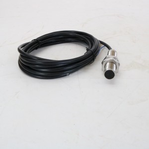
The SFS-2 magnetoresistive speed sensor operates by generating pulse signals based on changes in the magnetic gap between the probe and the turbine’s rotating components. The size of this magnetic gap, or the installation clearance, has the greatest impact on signal clarity.
The SFS-2 speed sensor should not be placed too close to the rotating component, nor too far away. Too close contact can cause probe wear and may also scratch the sensor due to vibration from rotating components. Too far away will weaken the magnetic field, resulting in a low pulse signal amplitude and easy overwhelm from interference signals. Generally, the recommended installation clearance for the SFS-2 is within a specific range (not requiring precision to multiple decimal places, but generally within a few millimeters). Please refer to the sensor manual for details. However, during actual installation, do not rely solely on theoretical values; adjustments must be made based on the actual conditions of the turbine’s rotating components.
To adjust the clearance, first stop the turbine, initially secure the SFS-2 speed sensor, and use a feeler gauge to measure the distance between the probe and the rotating component. Fine-tune the sensor position repeatedly until the clearance meets the requirements, then temporarily secure it. Then, manually rotate the turbine rotor and observe the pulse signal on the oscilloscope. If the signal amplitude is stable and without noticeable fluctuations, the clearance is appropriate. If the signal is intermittent or too low, adjust the clearance until the signal is clear.
Many people tend to overlook dynamic changes in the clearance during installation. For example, slight rotor movement during turbine operation can cause the clearance to increase or decrease. Therefore, when adjusting the clearance, consider the range of rotor movement and allow for a certain margin to prevent clearance abnormalities caused by movement during operation, which could affect the speed sensor’s signal output.
Installation Location: Avoid Interference Sources
There are many locations on a steam turbine where the speed sensor can be installed, but not all locations will produce a clear pulse signal from the SFS-2 speed sensor. Choosing the right installation location is a crucial step in optimizing installation.
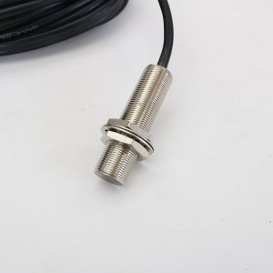
First, choose a location that is sensitive to signals on the turbine’s rotating components. This can be found at the intersection of tooth tops and valleys on the gear plate, or at designated bosses on the shaft. These locations experience the most pronounced changes in magnetic resistance, allowing the SFS-2 speed sensor to more easily detect magnetic field variations. The resulting pulse signal has a high amplitude, sharp edges, and naturally better clarity. Avoid locations on rotating components with smooth surfaces and no obvious bumps. In these locations, magnetic resistance changes are minimal, making it difficult for the speed sensor to produce a stable pulse signal.
Second, avoid sources of interference. Steam turbines are surrounded by many components that could interfere with the speed sensor signal, such as large motors, solenoid valves, and high-voltage cables. These devices generate electromagnetic fields during operation, which can easily superimpose on the SFS-2 pulse signal, increasing signal noise. Installation should be as far away from these interference sources as possible, or at least at a certain distance. If this is not possible, consider installing a shielding device, but this must be done after selecting the right installation location to reduce basic interference.
Also, pay attention to vibration conditions at the installation location. The vibration amplitude varies across different parts of the turbine during operation. Installing the SFS-2 speed sensor in a location with severe vibration can easily cause the sensor to loosen or shift, resulting in gap variations and signal degradation. Therefore, it is important to select a location with relatively low vibration levels, such as an area near bearings where vibration is relatively gentle, or a location on the turbine body with good rigidity, to minimize the impact of vibration on the speed sensor’s installation stability.
Fixation Method: Eliminate “Loosening Hazards”
If the SFS-2 speed sensor is not securely fixed after installation, vibration from turbine operation can cause the sensor to shift, widening or narrowing the gap, and naturally blurring or even losing the pulse signal. Therefore, optimizing the mounting method is key to ensuring the speed sensor maintains a clear signal over the long term.
First, use a dedicated mounting bracket. The SFS-2 speed sensor typically comes with a compatible bracket. The bracket is made of a durable, vibration-resistant material that securely holds the sensor in place. Avoid using improvised, homemade brackets, such as those made with wire or plastic. These lack strength and are prone to deformation and breakage under prolonged vibration, causing the sensor to loosen. When installing the bracket, ensure that it fits snugly against the turbine body without any gaps. When tightening the bolts, tighten them diagonally to avoid uneven force on the bracket and resulting in deformation.
Second, use anti-loosening bolts. Ordinary bolts are prone to loosening under prolonged vibration. Therefore, use anti-loosening bolts, such as those with anti-loosening washers or double-nut locking, to secure the SFS-2 speed sensor to the bracket. When tightening bolts, control the force to ensure they are securely fastened without excessive force that could break the bolts or damage the sensor housing. A torque wrench can be used to tighten the bolts to the torque value specified in the manual. If a torque wrench is unavailable, tighten the bolts until there is no noticeable movement.
After installation, a looseness test should also be performed. Manually shake the sensor and bracket to feel for any signs of looseness. Then, start the turbine and run it at low speed for a while. After shutting down, check again for loose bolts and sensor displacement. If looseness is detected, retighten the bolts and investigate the cause, such as incorrect bolt type or a loose fit between the bracket and the turbine body.
Wiring: Reduce Signal Loss and Isolate External Interference
The wiring of the SFS-2 speed sensor can also easily affect the clarity of the pulse signal. Improper wiring can cause signal loss and interference during transmission, resulting in a blurred output signal.
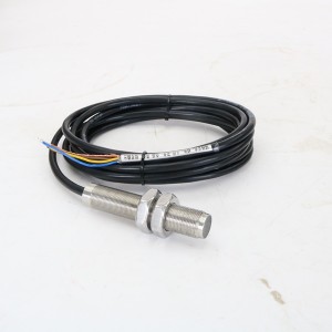
First, select an appropriate cable. The SFS-2 speed sensor has a dedicated signal cable with a shielded layer to reduce external electromagnetic interference. Do not use ordinary wire as a substitute. Ordinary wire lacks shielding and is susceptible to signal interference. Furthermore, the cross-sectional area and material of the conductors may not meet the requirements, resulting in signal loss. The cable length should be appropriate, neither too long nor too short. Excessive length increases signal transmission distance and causes amplitude attenuation. Excessive shortness can strain the terminals and cause the connections to loosen under prolonged vibration. If the installation requires a longer cable, use shielded cable with minimal signal attenuation and secure the cable appropriately in the middle to prevent it from shaking.
Secondly, ensure the terminals are securely fastened. When connecting the cable to the SFS-2 speed sensor’s terminals, first strip an appropriate amount of insulation to expose a clean, oxidation-free conductor. Insert the cable into the terminal and tighten with the screws. After tightening, gently tug on the cable to ensure it does not fall off. Loose terminals can cause poor contact, resulting in intermittent pulse signal loss or noise.
Also, ensure proper cable shielding. Ground the cable shield at one end, at the turbine’s ground terminal. Do not ground both ends. This can easily cause ground loops and introduce interference. The shielding layer must be securely connected, with no loose connections. For example, crimping with a crimping terminal before grounding prevents the shielding layer from falling off and causing shield failure. Furthermore, cables should be routed away from high-temperature areas of the turbine to prevent damage to the insulation. Cables should also be securely secured to prevent contact with rotating components and prevent wear.
As shown in the installation optimization of the SFS-2 magnetoresistive speed sensor, when selecting a speed sensor for a steam turbine, it is important to consider not only the sensor’s measurement range, accuracy, and vibration resistance, but also its installation compatibility. The speed sensor is the “eye” of the turbine speed monitoring system, and the clarity of its pulse signal directly determines whether this “eye” can accurately “see” speed changes. If the speed sensor output signal is fuzzy, the turbine’s speed control system may not be able to adjust the speed in a timely manner, and the protection system may malfunction or fail to operate, which in serious cases could affect the safe operation of the turbine. Therefore, prioritizing the installation optimization of the SFS-2 speed sensor is crucial not only for obtaining a clear pulse signal but also for ensuring safe turbine operation.
If your steam turbine still experiences pulse signal fuzziness or signal loss after installing the SFS-2 magnetoresistive speed sensor, or if you need to select a speed sensor suitable for your steam turbine or are unsure how to optimize the installation, please contact us:
E-mail: sales@yoyik.com
Tel: +86-838-2226655
Whatsapp: +86-13618105229
Yoyik offers various types of power plants spare parts for steam turbines, generators, boilers as below:
linear motion sensor TDZ-1-21
contactless displacement sensor DET-150B
Exciter Cabinet Gauge 3BHB006943R0001
intelligence Hand Operator NPDF-Q111FD5
control Panel CB-GEN5-HMI
ac lvdt LVDT TDZ-1-H 0-150
Magnetic flap level gauge UHZ-517C10L-1300
Magnetic speed sensor SMCB-01-16-070-03-01-01
GAUGE PRESSURE E3144232-02
Eddy Current Sensor PR6422/104-120
Bolt electric heating rod ZJ-20-T8
Cables CWY-DO-810800-50-09-02
intelligence Hand Operator NPDF-Q101
LVDT Sensor 4000TDGN-10-01-01
Eddy Current Sensor PR6424/001-131
intelligence Hand Operator NPDF-Q2113
Voltage Converter LJB1
Differential pressure alarm RCA218MZ089Z
pressure sensor alarm RC778NZ097Z
Pressure switch ST307-305-B
Online gas purity analyzer XACT500
LVDT Sensor HTACC-LT-303Z
Position control switch LXW2-1188
Eddy Current Sensor PR6423/002-010
thermal resistance sensor WZPM2-001 Pt100 L=50
electric iron element price CHK03.606.21Z
Magnetic Liquid Level Gauge UHZ-52Y000A-450-1.6
Electric heater JHG03S2-380V/6KW-A12X1500X2
Bolt electric heating rod ZJ-20-T9
liquid level indicator for tanks UHZ-10C00N
TSI Relay card A6500-RC
Post time: Sep-25-2025
-

LVDT Displacement Sensor DET100A
-

EH main oil pump inlet filter element OF3-20-3R...
-

High Temperature cylinder sealing grease MFZ-3
-

Duplex oil filter DQ150AW25H1.0S
-

Linear variable differential transformer DET200A
-

Gear Oil Pump GPA2-16-E-20-R6.3
-

Heat-resistance FFKM Rubber sealing O-ring
-

Bolt Electric Heater HY-GYY-1.2-380V/3
-

Servo valve SV4-20(15)57-80/40-10-S451
-

ZJ series steam turbine bolt heating rod
-

Surface cover epoxy air-dry varnish 1504
-

Generator Stator Cooling Water Filter SGLQ-600A