

Speed measurement in a steam turbine protection system isn’t something you can afford to get wrong. The TSI system relies on shaft speed data to decide when to trigger alarms and when to initiate an emergency trip. If the rotational speed sensor feeding that system is off by even a small margin, the protection setpoints you’ve carefully calibrated aren’t really doing what you think they’re doing.
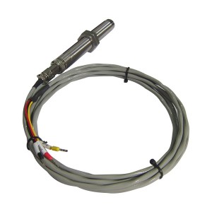
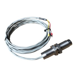
The DF6101-005-065-01-10-00-00 is a reluctance-type speed sensor built for this kind of application. It runs without external power — the signal comes entirely from the magnetic induction principle as gear teeth pass the sensor tip. The housing is stainless steel and completely sealed, with the internals potted solid. That matters in turbine environments where oil mist, steam, and condensation are just part of the everyday reality.
This article is specifically about accuracy. What does this sensor actually deliver at 3000 rpm, and is that good enough for TSI system requirements?
How the Signal Gets Generated
There’s a permanent magnet inside the sensor. When a ferromagnetic gear tooth passes through the magnetic field at the sensor tip, it changes the flux — that change induces a voltage in the coil. The output is a roughly sinusoidal signal, and the frequency tells you how fast the shaft is spinning.
The math is simple. At 3000 rpm with a 60-tooth target wheel, you get 3000 pulses per second — a 3 kHz signal. The TSI monitor counts those pulses over a set measurement window and converts it to an rpm reading. Nothing complicated about it, which is part of why this type of sensor has been the standard in turbine speed measurement for decades.
One thing worth knowing: because the signal is generated by shaft movement rather than an external supply, the output amplitude changes with speed. At slow roll during startup, the signal is weaker than at full rated speed. This isn’t a problem at 3000 rpm, but it does affect how the TSI monitor handles startup — the input threshold settings need to be low enough to pick up the signal during initial rotation.
What TSI Systems Actually Require for Speed Accuracy
Speed measurement for overspeed protection isn’t held to the same standard as, say, a process temperature reading. The stakes are different. For a 3000 rpm machine, the overspeed trip threshold is usually set somewhere around 3300 to 3360 rpm — roughly 110% to 112% of rated. That’s not a huge margin above normal operating speed.
If the speed measurement has significant error baked in, you’re either tripping too early or — worse — the actual shaft speed is already above the nominal trip setpoint before the monitor sees it. Neither is acceptable.
Most TSI system specifications require total speed channel error to stay within ±0.5% of reading at rated speed. Some tighter specs go to ±0.25%. That total covers the sensor, the signal conditioning, and the monitor itself. For the sensor’s individual contribution, you generally want it to be a small fraction of that total — ±0.1% or better — so the rest of the chain still has room to add its own small errors without blowing the budget.
What the DF6101-005-065-01-10-00-00 Delivers at Rated Speed
Here’s the thing about pulse-counting speed measurement: the accuracy question is fundamentally different from analog sensors. There’s no calibration drift in the traditional sense. The sensor isn’t producing a voltage that might shift 0.3% over temperature. It’s producing pulses, and each pulse corresponds to one tooth passing. The frequency is the speed.
The error sources that actually matter for this type of sensor are:
- Tooth spacing variation on the target wheel — this is a machining tolerance issue, not a sensor issue, and for properly manufactured gear wheels it’s typically within ±0.1%
- Jitter in the zero-crossing point on the sinusoidal output, which depends on how clean the signal is relative to the monitor’s detection threshold
- Any frequency response limitation at higher speeds — not relevant at 3000 rpm for a sensor in this class
At 3000 rpm with a correct installation gap and a decent target wheel, all three of those are small. The sensor-contributed error is comfortably within ±0.1%, which is what you need for the sensor portion of a TSI accuracy budget. The DF6101-005-065-01-10-00-00 meets TSI system requirements at rated speed when it’s installed correctly — that second part being the operative condition.
Installation Gap Is Where Things Actually Go Wrong
The sensor specification isn’t usually what causes measurement problems in the field. The gap between the sensor tip and the gear tooth crown is.
Reluctance sensors need to be close enough to the target wheel that the magnetic field interaction is strong. Too wide a gap and the signal amplitude drops. At rated speed this often still works — there’s enough tooth velocity to generate a reasonable signal even at a slightly wide gap. During startup at slow roll, though, a wide gap can mean the signal falls below the TSI monitor’s input threshold and the monitor reads zero speed when the shaft is actually turning. That’s a problem for turbine protection during roll-up.
The typical installation gap for the DF6101-005-065-01-10-00-00 is in the range of 0.5 to 1.5 mm, with 1.0 mm being the common target. Check the datasheet for this specific model variant to confirm. When you’re setting the gap, use a brass or plastic feeler gauge — not steel. A steel gauge gets pulled toward the permanent magnet and gives you a false reading of the actual clearance.
Once installed, check the signal amplitude at the TSI monitor input terminals during slow roll before the turbine gets to speed. Make sure the monitor is actually picking up the signal at the low end of the speed range, not just at rated speed.
Key Specs in One Place
| Parameter | Detail |
|---|---|
| Sensor type | Passive magnetic reluctance (variable reluctance) |
| Output signal | Near-sinusoidal AC voltage, frequency proportional to speed |
| Power supply | None — self-generating |
| Housing material | Stainless steel, fully sealed |
| Internal construction | Potted / fully encapsulated |
| Typical installation gap | 0.5–1.5 mm (confirm against datasheet) |
| Primary application | TSI system steam turbine rotation measurement |
| Accuracy at rated speed | Within ±0.1% at 3000 rpm with correct installation |
Why the Sealed Construction Matters for Long-Term Accuracy
Turbine enclosures are not a clean environment. Oil mist settles on everything. Steam condenses on cooler surfaces. Vibration is constant. A sensor with any unsealed internal air space will eventually let moisture in — and once moisture gets to the coil winding or the internal connections, the electrical characteristics start to drift in ways that aren’t predictable.
The DF6101-005-065-01-10-00-00 has its internals fully potted. There’s no air gap, no internal cavity. The coil, magnet, and wiring are encapsulated in solid compound. This is what keeps the sensor stable over years of operation in a turbine environment rather than requiring frequent recalibration or early replacement due to environmental degradation.
The stainless steel body handles the mild chemical exposure that comes from oil additive vapors and any steam chemistry in the surrounding air. For installations where the sensor is likely to have direct oil contact rather than just vapor exposure, double-check the IP rating for the specific installation scenario.
Redundant Speed Measurement — What to Keep in Mind
Most turbine protection systems don’t use a single speed sensor on its own. Two or three sensors on the same target wheel feeding separate monitor channels is the standard approach for overspeed protection. If one sensor fails, the voting logic keeps the system from spurious tripping. If one sensor reads high, the 2-out-of-3 arrangement prevents a missed trip.
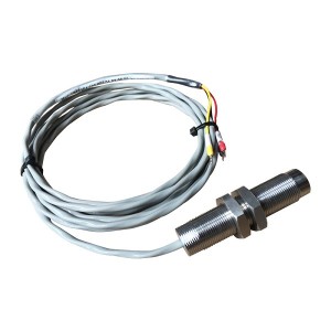
Because the DF6101-005-065-01-10-00-00 is self-generating with no external power supply, each sensor is electrically independent. There’s no shared supply rail that could take out multiple channels simultaneously — which is exactly the kind of common-cause failure that redundancy is supposed to guard against.
When specifying multiple sensors for a redundant installation, the thing to check upfront is monitor input impedance compatibility with the sensor’s output at low speeds. A monitor with an input threshold that’s set for full-rated-speed signal amplitude may not pick up the sensor during startup. Catching this in the specification phase is much easier than troubleshooting it during commissioning.
If you’re sourcing sensors for an upcoming outage or a new installation and want to confirm compatibility with your existing TSI monitors, it’s worth discussing the specifics with your supplier before the maintenance window opens rather than after.
When to Replace or Inspect
Reluctance sensors don’t wear out the way mechanical components do. There are no moving parts. In normal service with a properly set gap, they can run for many years without any change in performance. The sealed construction removes most of the degradation mechanisms that limit sensor life in harsh environments.
That said, a few situations do warrant closer inspection:
- Any event where the sensor tip may have contacted the target wheel — turbine rubs or severe vibration events can cause tip damage that changes the gap geometry or damages the internal coil
- Signal amplitude at rated speed has dropped noticeably compared to historical readings, without any change in installation gap
- Physical damage to the cable or connector — the cable is often more vulnerable than the sensor body, and a damaged cable can cause intermittent signal loss that looks like sensor failure
- Any installation where the cable entry seal may have been compromised by physical damage or improper routing
Checking signal amplitude at the monitor input terminals during routine maintenance rounds — not just verifying that the speed reading looks right — gives you early warning of gradual signal degradation before it becomes a protection gap.
Bottom Line
The DF6101-005-065-01-10-00-00 meets TSI speed measurement accuracy requirements at 3000 rpm. The sensor-contributed error at rated speed is within ±0.1% under correct installation conditions, which fits comfortably within the sensor’s share of a standard TSI accuracy budget.
The accuracy you get in practice comes down to installation gap, target wheel quality, and confirming the monitor’s input thresholds cover the full speed range from first rotation through rated speed. The sensor specification itself, for this application at this speed, isn’t the limiting factor.
Post time: Jul-13-2026
-

Intelligent Speed monitor HY-TACH
-

Single Channel Speed Monitor D521.02
-

EH oil actuator filter DP6SH201EA03V/-W for Ste...
-

977HP sealing oil differential pressure valve
-

Bimetal Thermometer Gauge WSS-411
-

Turbine Rotation Speed Impactor Monitor HZQW-03A
-

793 Room temperature curing epoxy dipping adhesive
-

DC Vertical lubricating oil pump 125LY-23-4
-

Magnetoresistive speed sensor SZCB-01-A1-B1-C3
-

Hydraulic oil filter element SDGLQ-25T-16
-

High Temperature steam turbine cylinder sealing...
-

Actuator EH oil filter with O-ring AP1E102-01D0...