

The WZP2-3.2/30/1.5/7 is a face-contact platinum thermal resistance designed specifically for measuring bearing pad metal temperature on steam turbines. It sits against the back of the bearing pad through a spring-loaded mechanism, and that direct contact is what makes it measure metal temperature rather than oil temperature. Getting the installation right matters more here than on almost any other sensor in the turbine — because if this one reads incorrectly, the bearing trip protection is working from bad data, and the only way to fix it is to lift the top casing.
What This Sensor Actually Measures — and Why It Matters
Steam turbine bearings use hydrodynamic oil films to prevent direct metal contact between the rotating shaft and the stationary bearing pad. The temperature of the bearing pad metal — the babbitt or white metal surface and the steel backing — is one of the primary indicators of whether that oil film is functioning correctly. Oil film breakdown, overloading, or contamination all show up as rising pad metal temperature before they cause visible damage.
A platinum thermal resistance (RTD) placed in oil would read oil supply or drain temperature, not bearing metal temperature. Those are different measurements with different alarm thresholds and different physical meanings. The WZP2 series uses a face-sensing element — a flat platinum sensing surface at the probe tip — that is specifically designed to measure the metal surface it contacts, not the oil surrounding it.
The trip protection system for bearing overtemperature relies on this sensor’s accuracy. In most turbine protection configurations, bearing metal temperature above a defined threshold (often 110–120°C depending on the bearing design) initiates a unit trip. A sensor that reads low due to poor installation will delay that trip. A sensor that reads high due to contact with the wrong surface will cause unnecessary trips. Both failure modes are operationally costly.
Sensor Construction and the Role of Spring Preload
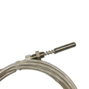
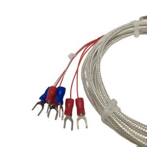
The model designation WZP2-3.2/30/1.5/7 encodes the key physical parameters: WZP indicates platinum resistance, the “2″ suffix indicates a dual-element configuration (two independent platinum resistance elements in one probe body), and the numerical sequence describes the probe diameter (3.2mm), insertion length (30mm), connection head dimensions, and other construction details.
At the probe tip is the face-sensing element — a small platinum resistance chip or coil embedded in a flat contact surface. Behind this tip, inside the probe body, is a spring mechanism. When the probe is inserted into the bearing housing installation bore, the spring is compressed against a shoulder in the bore. The spring force pushes the sensing face firmly against the back of the bearing pad and maintains that contact as the turbine goes through thermal cycles.
The spring is not decorative. Without adequate preload force on the sensing face, air or oil occupies the gap between the sensor tip and the bearing metal. Air and oil are poor thermal conductors compared to direct metal-to-metal contact. The sensor then reads the temperature of whatever fluid is in that gap — which tracks oil temperature, not bearing metal temperature. The two values can differ by 20°C or more under load.
Installation: How to Confirm the Sensor Has Seated Correctly
The installation bore for the WZP2-3.2/30/1.5/7 runs through the bearing housing from the outside to the back of the bearing pad. The bore diameter matches the probe diameter closely enough to guide the probe straight but loosely enough to allow insertion without force. The bore has a depth stop — a shoulder or a defined bottom surface — that positions the probe at the correct axial location relative to the bearing pad face.
As the probe is pushed in, it slides freely until the sensing tip makes contact with the bearing pad back surface, or until the spring compression begins — whichever comes first. From that point, continuing to push compresses the spring. The resistance to further insertion increases noticeably and progressively. This is the spring feedback that confirms the probe has reached the bearing metal contact zone.
Reading the Spring Feedback During Insertion
Push the probe into the bore slowly and steadily, with attention to the force required at each stage. The sequence should feel like this:
- Free sliding phase: The probe moves easily into the bore with minimal resistance. The sensing face has not yet reached the bearing pad. This phase covers most of the insertion depth.
- Initial contact: Resistance increases noticeably as the sensing face touches the bearing pad back surface. The change in force is distinct — from almost nothing to a definite resistance. This is the start of spring compression.
- Spring compression zone: Continuing to push compresses the spring further. The force required increases progressively as the spring deflects. The probe should be pushed until the mounting flange or the installation hardware bottoms out against the housing, not until the force simply becomes high. The spring compression depth is designed to be consumed by the time the probe is at its fully installed position.
If the probe reaches its fully installed position — flange seated, installation hardware engaged — without ever feeling increased resistance during insertion, the sensing face did not contact the bearing pad. Possible causes: the bearing pad is not in its correct axial position, the installation bore is deeper than nominal, or the probe is shorter than specified for that application. Do not proceed without investigating.
Confirming Contact After Installation
After the probe is installed and secured, a quick resistance measurement at the connection head confirms the sensing element is intact. For a standard Pt100 platinum thermal resistance at ambient temperature, the measured resistance should be close to 100 Ω (at 0°C, 108–110 Ω at 25–30°C). A very high reading or open circuit means the element was damaged during installation or was already defective. A very low reading indicates a short in the element or the lead wires.
A more definitive confirmation of correct contact comes after the turbine comes online. Compare the bearing metal temperature reading from this sensor against the adjacent bearing or against the oil drain temperature from the same bearing. A sensor in good contact with the bearing pad will show a temperature noticeably higher than the oil drain temperature at any significant load — typically 15°C or more above drain temperature at moderate load. If the reading tracks oil drain temperature closely, recheck the installation.
Why Poor Installation Is Hard to Detect Until It’s Too Late
A platinum thermal resistance with inadequate contact pressure will still produce a reading. The DCS will show a value, the trend will look plausible, and nothing will generate an alarm — because the sensor is reading oil temperature, and oil temperature on a normally loaded turbine bearing is within expected limits. The bearing metal could be running 30°C hotter than what the DCS shows, and the protection system would not respond.
This failure mode is silent. It shows up only when a bearing actually overheats and the trip that should have fired at 115°C fires instead at 140°C — or doesn’t fire at all. That’s why installation confirmation is not optional for this sensor type.
The same risk applies to sensors that were correctly installed but have lost contact over time. Thermal cycling can cause slight axial shifts in bearing housing components. If the spring was installed at the lower end of its compression range, small shifts may be enough to break the contact. Periodic verification of bearing temperature sensor readings against oil temperature at defined load points — as part of a condition monitoring programme — catches this before it becomes a protection failure.
Common Installation Errors and Their Symptoms
| Installation Error | Symptom at the DCS | Verification Method |
|---|---|---|
| Probe inserted without spring compression — sensing face not in contact | Bearing temperature tracks oil temperature; no significant rise above drain temperature at load | Pull probe, check insertion depth against probe length and bore depth; look for absence of spring compression marks on housing shoulder |
| Probe installed at angle — sensing face touching bore wall, not bearing pad | Unstable reading; erratic values that don’t correlate with load or temperature changes | Remove probe and check tip face for contact marks; verify bore alignment is straight |
| Spring fully compressed before flange seated — excess preload | Reading may appear normal but probe body is under excessive stress | Measure bore depth and compare to probe insertion length; check for binding during installation |
| Probe correct but lead wire connection reversed (dual-element) | One element reads correctly, the other shows open circuit or unexpected value | Resistance measurement at each element at ambient temperature; should both read close to 100 Ω for Pt100 |
| Contamination on sensing face — oil film or debris between face and bearing pad | Reading lower than expected; slow thermal response when load changes | Remove probe and clean sensing face; reinstall and compare response speed at next load change |
Why Replacement Requires a Full Casing Lift
The WZP2-3.2/30/1.5/7 installs through the bearing housing with the sensing face against the back of the bearing pad — a surface that is only accessible when the turbine is disassembled. The installation bore reaches the bearing from outside, but the bearing pad itself is contained within the turbine’s lower casing. To remove or replace the probe, the top casing must be lifted and the rotor and bearing assembly must be accessible.
This is why getting the installation correct the first time carries more weight here than for most other sensors in the turbine. A thermocouple on a steam pipe can be swapped during a brief outage. A flow transmitter on a service line can be replaced without major disassembly. The bearing metal temperature platinum thermal resistance on a large steam turbine cannot. It goes in once per major overhaul, and it stays until the next one.
The consequence of a failed or misread sensor is not just an inaccurate trend on the DCS. It is a protection system that is operating on incorrect data for the months or years between overhauls — a risk that justifies the time taken to confirm the installation correctly before the casing is closed.
E-mail: sales@yoyik.com
Tel: +86-838-2226655
Whatsapp: +86-13618105229
Yoyik offers various types of power plants spare parts for steam turbines, generators, boilers as below:
Electronic Module P223CB01BD5
Preamplifier 330780-50-00
Eddy Current Sensor PR6422/000-010
YOYIK® LVDT Sensor TDZ-1E-32
Electric motor Y2-132M-4
Expansion indicator HPSQ-150\220*250
MCB 1P IC65N D 16A
axial Displacement Monitor HZW-D
Excitation transformer DG-10000VA
LVDT Sensor 4000TDGN-100-01-01
PRESSURE TRANSMITTER 3051CD1A22A1BM5E5Q4HR5
Input board DZXL-ZL-E-6682/32
Speed probe CSG0650501
pt100 sensor manufacturer TR-301-306
Transmitter 3051CD3A22A1AM5B4DF
PH digital display meter LEX2000.01
Digital Input Module XGI-D22A
Eddy Current Sensor PR6426/000-100
TURBINE SPEED SENSOR CS-02
transmitter XCBSQ-03/080-01-01
TRANSFORMER QDSC-YM5WDI-8/18.7*8/15
honeywell linear position sensor TDZ-1
safety pressure switch 460983-QFA015
lvdt displacement transducer C9231120
Post time: Jun-04-2026
-

KR-939SB3 Integrated Three-Parameter Combinatio...
-

Epoxy Phenolic Anti-Corona Laminated Glass Clot...
-

Heat-resistance FFKM Rubber sealing O-ring
-

CS-V hydraulic system filter Differential press...
-

WZPM2-001 PT100 Platinum thermal resistance The...
-

AST/OPC solenoid valve SV4-10V-C-0-00
-

Generator stator RTV epoxy adhesive J0708
-

DN80 Sealing oil vacuum tank floating valve
-

EH oil regeneration Alumina Filter 30-150-219
-

YCZ65-250C generator stator cooling water pump
-

High-pressure jacking oil Pump P.SL63/45A
-

Hydraulic oil station precision fine filter UE3...