In power plants, as a common power transmission device, accurate control of the stroke of the actuator is crucial to ensure the normal operation of the equipment. The LVDT displacement sensor HL-6-50-15, as a high-precision position detection device, can effectively monitor and control the stroke of the actuator. But its monitoring accuracy is affected by the performance of the sensor itself and the quality of the wiring. Today we will learn about the impact of the wiring of displacement sensors on their performance.
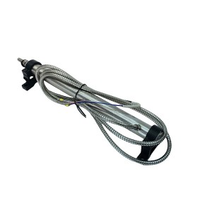
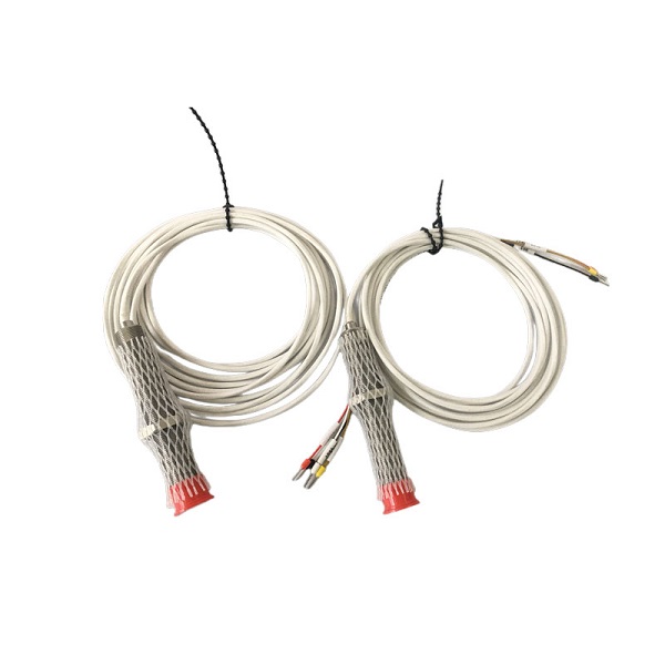
The output signal of displacement sensor HL-6-50-15 is usually very weak, so high-quality connectors and cables are needed to transmit the signal to reduce signal loss and interference. When wiring, ensure good contact at the connection points to avoid signal fluctuations caused by poor contact.
In addition, electromagnetic interference in the wiring environment may also affect the stability of the sensor. The response time is affected by the internal circuits and wiring circuits of the sensor. If the wiring resistance is high or the cable is long, it may cause signal transmission delay, thereby affecting the response time of the sensor.
The wiring configuration of sensors also needs to consider safety. If the wiring is improper, it may cause short circuits, overloads, or other electrical faults, thereby affecting the safety of equipment and personnel.
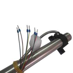
In order to ensure the good performance and safety of the displacement sensor HL-6-50-15 in the monitoring of actuator travel, we propose the following wiring suggestions:
1. Use high-quality connectors and cables to ensure good contact and signal transmission quality.
2. Use shielded cables to reduce electromagnetic interference and ensure that the contact points between connectors and sensors are clean and secure.
3. Use low resistance connectors and cables, and try to shorten the cable length as much as possible to reduce signal transmission delay.
4. Follow the wiring instructions and electrical specifications of the sensor to ensure a reasonable layout of the circuit and sufficient electrical clearance.
Post time: Mar-04-2024


