

When a gas turbine starts showing load fluctuations or the steam valves are responding slower than they should, the G771K202A servo valve is usually one of the first things that comes up. It sits right between the DEH control system’s electrical output and the hydraulic actuator that actually moves the valve — and when something goes wrong in that chain, the turbine feels it pretty quickly.
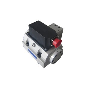
The G771K202A is a two-stage electro-hydraulic servo valve. There’s a nozzle-flapper pilot stage that picks up the milliamp control signal and a four-way spool output stage that turns that response into real hydraulic flow to the actuator. Both stages can fail on their own, and they fail differently. The tricky part is figuring out which one is actually causing the problem before you start pulling things apart.
What This Valve Is Actually Doing in the DEH System
The DEH system manages the position of the turbine’s steam valves — HP main stop valves, HP control valves, reheat stop valves, reheat intercept valves. These control how much steam gets into the turbine, which determines power output and speed. The servo valve is the link between the digital control signal and the physical valve movement.
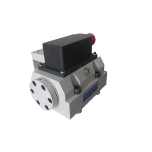
The signal coming into the G771K202A is tiny — a few milliamps of differential current from the DEH controller. The pilot stage takes that signal and turns it into a pressure difference across the spool. The spool shifts, EH oil goes to one side of the actuator piston while the other side exhausts, and the actuator moves. The DEH system watches the actual valve position through a feedback transducer and keeps adjusting the signal to close the error.
The nozzle-flapper design is what gives the valve its speed and sensitivity. The flapper sits between two small opposed nozzles with oil flowing continuously through both. A tiny deflection from the torque motor — responding to the control current — unbalances the flow between the nozzles, and that pressure imbalance pushes the spool. It’s a precise arrangement, which is exactly why contamination causes so much trouble here. Those nozzle orifices are small enough that fine particles in the EH oil can block them with very little warning.
Three Things That Can Cause the Same Symptom
Load hunting and slow valve response can come from three different places, and they look nearly identical at the system level. Getting this right before doing anything to the valve saves a lot of wasted effort.
Pilot Stage Blockage
If contamination has partially clogged one or both nozzles, the pressure differential driving the spool becomes uneven or sluggish. The spool stops responding proportionally. At mild blockage the valve still moves but it’s slow and the DEH position error grows. At worse blockage, one direction of movement gets noticeably more restricted than the other.
The tell-tale sign of pilot stage blockage — rather than a spool problem — is asymmetry. If the valve opens normally but closes slowly, or the other way around, the nozzle restriction is a strong suspect. The DEH position tracking data shows this clearly if you look at whether the error is larger in one direction during a ramp test. That asymmetry is hard to get from spool wear alone.
Spool Wear or Sticking
The output spool runs in very tight clearance inside the valve bore. Particles too large for the nozzle orifices can still get into the spool clearance and increase friction over time. Abrasive wear on the spool lands and bore increases internal leakage across the spool — the valve delivers less net flow to the actuator for a given spool position, and the actuator drifts when it should be holding.
With spool wear, the main symptom is usually continuous low-amplitude hunting around the setpoint. The DEH controller is constantly applying small corrections to compensate for an actuator that won’t sit still. And unlike pilot stage problems, the hunting tends to be roughly equal in both directions. If the position instability is symmetric and persistent, worn spool lands are more likely than a nozzle issue.
DEH Signal Problems
Before touching the servo valve, check the signal. A drifting command from the DEH controller, a bad cable connection, or a failing position feedback transducer can produce exactly the same symptoms at the actuator. There’s no point cleaning or replacing the servo valve if the problem is upstream of it.
Check the actual milliamp signal at the servo valve coil terminals while the fault is happening. If the command signal looks clean and stable but the actuator isn’t responding correctly, the valve is the likely cause. If the signal is noisy or drifting, that’s where the investigation needs to go first. This check takes a few minutes and should always happen before anything else.
Can You Clean the Pilot Stage and Get the Performance Back?
Sometimes — but it depends on what caused the blockage and whether any physical damage happened along the way.
If the nozzle blockage is from loose contamination that hasn’t eroded the nozzle geometry, ultrasonic cleaning of the pilot stage components can work well. Some teams flush the pilot stage with clean solvent while the valve is isolated from the system, though you need to be careful not to push debris deeper into the orifices.
What cleaning can’t fix is physical damage. If abrasive particles have worn the nozzle orifice or scored the flapper pivot, the flow characteristics of the cleaned valve won’t match the original calibration. The valve might function, but its gain, null position, and frequency response will all be off. In a DEH system where the control loop is tuned around specific servo valve parameters, that matters — you can end up with a valve that passes a basic function check but causes stability problems in operation.
Cleaning makes sense as a recovery measure when the fault onset was recent and there’s been a confirmed contamination event in the system. For a valve that’s been slowly degrading over months, or one that failed during a pressure or temperature excursion, a full overhaul and recalibration is the more reliable path.
What the Post-Repair Test Report Should Actually Show
This is the part that doesn’t get enough scrutiny when a repaired servo valve comes back from an overhaul shop. A report that just says “tested OK” or “function verified” isn’t good enough for a component in this position. You need measured numbers, compared against the original design specification, for each of the following:
- Null offset (zero bias): The control current needed to hold the spool exactly centered. Should be within a narrow band — typically ±1 to 2% of rated current. A large null offset means the valve is biased toward one direction at rest, which the DEH controller has to fight continuously.
- Hysteresis: The difference in output when the same input is approached from opposite directions. High hysteresis causes positioning error every time the valve changes direction. Typically specified below 3 to 5% of rated output.
- Frequency response: How well the valve tracks an oscillating input signal across a range of frequencies, reported as the -3dB bandwidth. This is probably the most important parameter for DEH loop stability. A valve with degraded frequency response limits how tightly the position loop can be tuned without going unstable.
- Internal leakage at null: How much oil flows across the spool when it’s centered and both actuator ports should be blocked. High null leakage means spool clearance wear, which generates heat in the EH system and will get worse over time.
- Threshold: The smallest input change that produces a detectable output. High threshold means the valve ignores small correction signals from the DEH controller, which shows up as poor fine positioning.
- Linearity: How closely the input-output relationship follows a straight line across the full range. Poor linearity means the control loop behaves differently at different operating points.
Each of these should be a number with a pass/fail against specification — not a description. If the repair shop can’t provide that, it’s worth asking why before accepting the valve back.
Key Test Parameters at a Glance
| Parameter | Why It Matters | Typical Spec Range |
|---|---|---|
| Null offset | Affects steady-state position accuracy | ±1–2% of rated current |
| Hysteresis | Causes position error on direction reversals | <3–5% of rated output |
| Frequency response (-3dB) | Sets the limit on control loop bandwidth | Typically >80–100 Hz for turbine valves |
| Null leakage | Indicates spool wear and system heat load | Per manufacturer spec — rises with wear |
| Threshold | Minimum detectable correction — affects fine control | <1% of rated input |
| Linearity | Affects how consistently the loop behaves across range | ±1–2% of full scale |
EH Oil Cleanliness — Why the Repair Won’t Last if This Isn’t Right
A freshly overhauled and calibrated G771K202A going back into a system with dirty EH oil will start accumulating contamination in the pilot stage nozzles from day one. How fast it degrades back to the pre-overhaul condition depends on how far outside spec the oil cleanliness is running.
ISO 4406 levels of 15/13/10 or better are what these valves need for decent service life in gas turbine EH systems. Running at 17/15/12 or worse shortens nozzle and spool life significantly — you’ll be back in the same situation in a fraction of the normal interval.
If servo valve faults are coming back sooner and sooner after each repair or replacement, oil cleanliness is almost always involved. Checking EH oil particle count and acid number before reinstalling the repaired valve, and fixing any deficiencies before startup, is probably the single most useful thing you can do to protect the overhaul investment.
If you’re evaluating repair facilities for the G771K202A or sourcing a replacement, asking for a sample test report upfront is completely reasonable — any reputable shop will have one. The data in that report is what tells you whether the valve coming back will actually perform to the specification your DEH system was tuned around, or whether you’re installing something that looks fine on the bench but won’t hold up in service.
Post time: Jul-07-2026
-

Stainless Steel Hydraulic Oil Filter 0850R020BN3HC
-

High Pressure Welding Angle Globe Valve J64Y-64
-

Actuator EH oil filter with O-ring AP1E102-01D0...
-

Low resistance anti-corona tape
-

Magnetic Rotation Speed Sensor ZS-01
-

Boiler anti-blocking air pressure sampler PFP-B-II
-

Duplex oil filter DQ150AW25H1.0S
-

Oil filter coarse filter DR913EA10V/-W
-

Hydraulic Pressure Control Valve PCV-03/0560
-

Rotational Speed Monitor MSC-2B
-

25CCY14-190B Jacking oil axial piston pump
-

Hydraulic lubricating oil station filter ZNGL02...