

Hydrogen-cooled generators are not quiet machines to build valves around. Between the rotating shaft line, the hydrogen coolers, and the piping that ties the whole cooling loop together, a valve sitting anywhere near this equipment lives with constant low-level shaking for years at a time. The WJ40F1.6P-II is a bellows-sealed globe valve, and its main selling point isn’t flow capacity or pressure class — it’s that it’s built to survive exactly this kind of environment without the stem seal degrading over time. Whether that promise holds up in practice depends a lot on where the valve sits and which vibration source is actually doing the damage.
Why Bellows Sealing Exists in the First Place
A conventional globe valve uses a packing gland around the stem — rings of compressible material squeezed tight enough to stop leakage but loose enough to let the stem move. That’s a fine solution for most services, but it has a known weakness: packing wears, and once it wears, hydrogen can find a path along the stem. For a hydrogen-cooled generator, that’s not a small risk. Hydrogen is light, it leaks past seals that would hold heavier gases just fine, and it’s flammable across a wide concentration range.
A bellows-sealed design gets rid of the packing gland entirely for the primary seal. Instead, a metal bellows — a thin-walled, corrugated tube — is welded between the stem and the bonnet. It flexes as the stem moves up and down, and because it’s a fully welded metal barrier, there’s no dynamic seal for hydrogen to sneak past. The packing is still there in most designs, but as a backup rather than the primary containment.
The catch with any bellows is fatigue. Every open-close cycle flexes the metal, and metal fatigue is cumulative. A bellows that’s been vibrating for years, even if nobody’s touched the handwheel, has been quietly accumulating stress cycles the whole time.
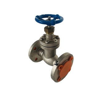
Where This Valve Actually Sits
In a hydrogen-cooled generator system, valves of this type typically show up in the hydrogen supply and vent piping, the gas control manifolds, and sometimes on instrumentation lines tied into the cooling system. These locations put the valve in reasonably close proximity to rotating machinery and to the coolers themselves — not bolted directly onto the generator casing usually, but close enough on connected piping that mechanical vibration transmits through the pipe wall and the support structure.
That’s really the core of the engineering question here. There isn’t one vibration source acting on the valve. There are at least three, and they don’t behave the same way.
Three Different Vibration Sources, Three Different Signatures
Turbine shaft-line vibration. This is typically the dominant, most rhythmic source. A turbine-generator shaft line runs at a fixed rotational speed (commonly a narrow band around the grid frequency, such as near 3000 or 3600 RPM depending on the system), and any imbalance, misalignment, or bearing wear on that shaft produces vibration at a very consistent frequency. This vibration transmits through the generator casing and foundation into connected piping, though the amplitude drops off with distance and depends heavily on how well the piping is supported and isolated.
Hydrogen cooler vibration. Coolers mounted with fans or associated with cooling gas circulation can introduce their own vibration, often at a different frequency than the shaft line — tied to fan blade pass frequency or to structural resonance of the cooler housing itself. This tends to be more localized; a valve mounted close to the cooler feels it more than one further down the line.
Pipeline fluid pulsation. Gas flow through the piping, especially near control valves, orifices, or where flow direction changes sharply, can produce pressure pulsation. This is a different mechanism entirely from mechanical vibration — it’s the fluid itself exciting the pipe wall and anything attached to it, and it tends to be more random or broadband rather than a single clean frequency.
Of these three, shaft-line vibration is usually the one engineers worry about most for a valve on connected piping, simply because it’s continuous, present at all times the unit is running, and often the largest-amplitude source in terms of energy transmitted into the structure. Cooler-induced vibration matters more for valves mounted close to the cooler skid. Fluid pulsation is usually smaller in amplitude but can excite a bellows if its frequency happens to land near a natural frequency of the bellows assembly — which is a coincidence that’s hard to predict without actual vibration measurement.
How the Valve Is Designed to Handle This
Two design features work together here, and it’s worth being clear that they solve different problems.
The anti-rotation structure keeps the valve stem from rotating relative to the bellows as the handwheel is turned to open or close the valve. This matters because the bellows is not built to twist — it’s built to flex axially, extending and compressing along the stem’s line of travel. If the stem were allowed to rotate freely inside the bellows during operation, the corrugations would experience a torsional stress they weren’t designed for, and that shortens fatigue life significantly, sometimes dramatically. The anti-rotation feature — commonly a pin, key, or spline arrangement between the stem and the bonnet — forces the stem to travel in a straight line without twisting the bellows.
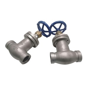
The vibration-resistant design, separately, addresses the ambient shaking transmitted through the valve body and piping, independent of whatever the operator is doing with the handwheel. This typically involves reinforced bonnet-to-body connections, a stiffer overall structure to shift the assembly’s natural frequency away from common excitation frequencies in the plant, and sometimes additional bellows support to limit how much the bellows itself can flex laterally under external shaking rather than just axial stem motion.
Together, these two features address the two different ways a bellows can fail under vibration. Anti-rotation prevents torsional fatigue from operational cycling. The vibration-resistant structure limits fatigue from continuous ambient shaking that has nothing to do with whether anyone’s operating the valve. A valve that only solved one of these problems would still be vulnerable to the other.
Reading the Signs of Trouble
Bellows fatigue failure doesn’t usually announce itself dramatically. The more common pattern is a hydrogen leak that develops gradually at the bonnet area, sometimes picked up first by a fixed hydrogen detector or during a routine leak survey rather than by any obvious symptom at the valve itself.
When that happens, there are a few possible explanations worth separating out.
If the leak coincides with the valve having gone through an unusually high number of open-close cycles — more than its typical service history — mechanical fatigue from repeated operation is a reasonable first suspect, particularly if the anti-rotation mechanism has any play or wear in it that would have let some torsional stress creep in over time.
If the valve has barely been operated but the leak still developed, and the valve happens to be mounted close to a cooler or on a run of piping known to vibrate more than others in the system, ambient vibration fatigue becomes the more likely explanation. This is where vibration monitoring data — if the plant collects it on nearby rotating equipment — becomes genuinely useful, because it can confirm whether vibration levels near that valve location have been elevated or trending upward.
It’s also possible, though less common, that a manufacturing defect in the bellows itself or a welding flaw at the bellows-to-stem or bellows-to-bonnet joint initiates a crack that has nothing to do with either operational cycling or ambient vibration. This is harder to distinguish without a metallurgical failure analysis, and it’s one reason bellows valves used in hydrogen service often get periodic non-destructive testing rather than being run to failure.
None of these three can be confirmed just by noting that a leak occurred. Cycle count history rules some scenarios in or out but doesn’t identify vibration frequency. Vibration data at the valve location can support the ambient-fatigue theory but can’t rule out a pre-existing weld flaw. A physical inspection of the failed bellows — looking at the crack initiation point and its orientation relative to the corrugations — is usually the step that actually distinguishes torsional fatigue, axial fatigue from ambient vibration, and a manufacturing defect from one another.
Inspection and Maintenance in Practice
For valves in continuous hydrogen service, periodic leak testing around the bonnet and stem area is standard practice, and any positive reading should prompt a closer look rather than just a re-tightening. Where accessible, checking the anti-rotation mechanism for play during a scheduled outage is worthwhile — a small amount of wear there compounds over years of cycling.
Vibration measurement at the valve mounting point, taken during normal generator operation, gives a plant-specific answer to which of the three sources discussed earlier is actually dominant at that location, rather than relying on general assumptions. This is more useful during initial installation planning or after a valve relocation than as routine ongoing maintenance, but it’s worth doing at least once if bellows failures have been a recurring issue at a particular location.
What to Confirm Before Ordering
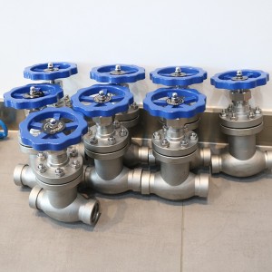
For a bellows-sealed globe valve intended for hydrogen-cooled generator service, buyers should confirm the bellows fatigue life rating or expected cycle life from the manufacturer, the materials used for the bellows and how they suit hydrogen exposure and the operating temperature range, whether the anti-rotation mechanism is a standard feature or an added option, and the pressure and temperature ratings against the actual system conditions rather than nameplate assumptions carried over from a similar unit elsewhere in the plant.
It’s also reasonable to ask whether the manufacturer has vibration test data or qualification specific to the anticipated service environment, since a valve rated generically for vibration resistance and one specifically qualified for rotating-machinery-adjacent service aren’t necessarily the same thing. Where this information hasn’t been provided, it shouldn’t be assumed, and it’s worth requesting directly rather than inferring from a general product description.
Closing Thought
The vibration problem for a bellows-sealed valve near a hydrogen-cooled generator isn’t really one problem — it’s three sources layered on top of each other, each with its own frequency signature and its own failure pathway. Shaft-line vibration tends to be the most persistent and often the largest contributor for valves on connected piping, cooler vibration matters most locally, and fluid pulsation is the wildcard that depends on where its frequency happens to land relative to the bellows assembly. Anti-rotation and vibration-resistant structure aren’t solving the same problem, even though they get talked about together — one stops the stem from twisting the bellows during normal operation, the other keeps ambient shaking from fatiguing it independently. Understanding which mechanism actually failed, when it does fail, takes more than a leak alarm. It takes cycle history, vibration data, and usually a look at the bellows itself.
Post time: Sep-07-2026
-

LVDT Position Sensor TD-1 0-100
-

YSF series pressure relief valve for transformer
-

SHV4 EH oil system needle globe valve
-

Boiler Air Preheater Infrared array probe HSDS-...
-

Dry-type Transformer Cooling Fan GFD590/126-710
-

Electrical Insulation Alkali-free FiberglassTap...
-

Oil pump outlet oil filter element DP906EA03V/-W
-

Globe valve SHV25
-

EH oil regeneration filter ZX-80
-

F3-V10-1S6S-1C20 DEH system EH oil circulating ...
-

Rotational Speed Monitor MSC-2B
-

Servo valve SV4-20(15)57-80/40-10-S451