

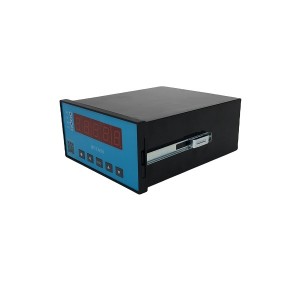
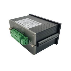
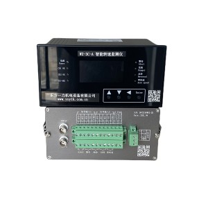
If you’ve ever commissioned a turbine protection loop, you know the direction question always comes up sooner or later. A speed meter might be reading the correct RPM and still get the direction wrong, and that’s a real headache when your Emergency Trip system logic depends on knowing which way the shaft is actually turning. The XJZC-03A/QF, also known as a speed bolt monitor in some plants, is built to handle this — but only if the sensors go in the right way and the settings match the physical setup.
This article walks through sensor placement, how to actually test direction on-site before you sign off, and where to look first when the direction comes out backwards.
Why You Need Two Sensors for Direction
One speed sensor tells you how fast something’s spinning. That’s it. It can’t tell you which way. To get a real forward/reverse reading, the XJZC-03A/QF uses two rotational speed sensors mounted around the same gear, picking up pulses that are slightly out of sync with each other.
The controller looks at the timing gap between the two pulse trains and figures out direction based on which one leads. This only works if the spacing and alignment between the sensors sits within a fairly tight range — get that wrong and the phase relationship gets shaky, sometimes flipping direction at certain speeds for no obvious reason.
Sensor Placement and Spacing — What Actually Matters
The two sensors need to be close enough that they’re reading the same teeth in a predictable order, but not so close that the phase difference becomes too small to measure reliably. That second part gets especially tricky at low speed, like during startup or coast-down, when pulse timing naturally slows down and gets less crisp.
Spacing is usually defined as a fraction of one gear tooth pitch, not just some fixed distance in millimeters. That’s important because tooth pitch changes depending on gear module, so you really can’t copy spacing numbers from a different turbine with a different gear and expect it to work the same.
Gear Tooth Profile and Module — Don’t Skip This
The speed gear itself needs a consistent tooth shape all the way around. If a few teeth are worn down or damaged, that throws off the phase timing between sensors, and you’ll start seeing weird intermittent direction readings that are hard to explain otherwise.
Module selection matters too. Go too fine and the pulses come out weak and noisy. Go too coarse and you lose resolution at low speed, which is exactly the range where direction accuracy matters most for trip logic.
- Check that the gear module actually matches what the sensor manufacturer recommends, not just whatever gear happened to be available.
- Look over the tooth profile for wear or chips before finishing sensor alignment, especially if this is a retrofit on an older turbine.
- Make sure the air gap is the same on both sensors — uneven gaps mess with the phase comparison even when spacing is technically correct.
| Parameter | Requirement |
|---|---|
| Sensor count | Two, positioned for phase comparison |
| Sensor spacing | Fraction of gear tooth pitch, based on module |
| Gear tooth profile | Even, no damage, consistent pitch |
| Air gap | Same on both sensors, within tolerance |
Testing Direction During Commissioning
Once everything’s mounted and wired up, the real test is just running the equipment and watching if the speed meter reports direction correctly. You can’t really confirm this on paper — it has to be checked on the actual machine, moving.
The usual way to do this is a jogging test. Engage the turning gear or barring device, jog the shaft forward at low speed, and watch the XJZC-03A/QF display to see if it says forward. Then, if the setup allows reverse jogging, do the same thing in reverse and check that the reading flips.
How to Run the Field Jogging Test
- Engage the turning gear and jog the shaft forward, slowest speed you can manage.
- Watch the direction shown on the meter or DCS screen — does it match what you know is actually happening?
- Stop, then jog reverse if your setup supports it, and check the display flips over correctly.
- Bump the jog speed up a little and repeat, just to make sure the reading holds steady and wasn’t a fluke at one speed.
It’s worth having someone actually watching the shaft or coupling during this, not just trusting the screen — at least the first time you’re setting this up on a new install.
Direction Reading Is Wrong — Now What?
When the jogging test shows the wrong direction, there’s really only two places it’s coming from: the sensor wiring, or the meter’s parameter settings. Check them in that order and you’ll save yourself some time.
Wiring — Check This First
Figure out which sensor is physically in the “leading” spot and which one’s “lagging,” based on which way the shaft actually turns. If someone swapped the two sensor cables during install — which happens easily enough on a crowded turbine deck — the meter’s going to read direction backwards even though nothing else is actually wrong.
- Trace each cable from the sensor itself back to its terminal on the XJZC-03A/QF. Don’t just trust the labels — labels get put on wrong sometimes.
- Double check sensor 1 and sensor 2 are wired the way the installation drawing says for forward direction.
- Look for loose connections too, since those tend to cause weird intermittent readings rather than a clean forward/reverse flip.
Parameters — Check This Second
If the wiring’s fine and the sensors are definitely hooked up correctly, look at the meter’s configuration next. Most units like this have a setting that decides which sensor counts as the phase reference — if that setting doesn’t line up with how things are actually wired, you get inverted direction logic even with perfect wiring.
Going through the parameter list against your commissioning paperwork usually sorts this out fast — don’t just assume the factory default is right for your install. It’s also worth asking whether anyone updated the firmware or config after the original setup, since that can reset direction settings and nobody notices until testing.
Why This Actually Matters for Trip Logic
Steam turbine speed control and emergency trip systems aren’t just watching RPM. Direction matters for barring gear interlocks, for catching reverse rotation under fault conditions, and for getting startup sequencing right.
A speed meter that gets direction wrong, even for a short time during commissioning, can trigger confusing alarms or hide a real mechanical problem somewhere else in the drivetrain. Getting sensor spacing, gear specs, and direction testing right before handover saves you from chasing false alarms once the unit’s actually running.
If you’re planning commissioning for an XJZC-03A/QF, it’s worth asking the manufacturer for their sensor spacing and gear module reference sheet ahead of time — makes field alignment a lot easier to check against real numbers instead of guessing.
Final Thoughts
The XJZC-03A/QF speed bolt monitor works well when the mechanical side is done right — spacing calculated against the actual gear module, tooth profile checked for wear, direction confirmed with a real jogging test instead of just trusting the wiring diagram. When direction comes out wrong, checking wiring first and parameters second usually gets you the answer without much guessing involved.
For anything feeding into emergency trip logic, spending a few extra minutes verifying direction during commissioning beats chasing a mystery fault after the turbine’s already spinning.
Post time: Aug-11-2026
-

Magneto electric Rotation Speed Sensor ZS-02
-

EH oil main pump skeleton oil seal TCM589332
-

AXIAL DISPLACEMENT MONITOR HZW
-

Three valve manifold HM451U3331211
-

Insulation Alkali-Free Fiberglass tape ET60
-

Jacking oil pump suction filter SFX-660×30
-

EH Oil Main Pump Discharge Oil Filter Element D...
-

Insulating box filling adhesive J0978
-

793 Room temperature curing epoxy dipping adhesive
-

Booster pump oil throw sleeve HZB253-640-01-06
-

TDZ-1E series linear displacement transducer LV...
-

Cellulose filter element LX-DEA16XR-JL